1 bl-u1 connections, 1 connecting the ac power supply, 2 connecting the bl-u1 to a bl series – KEYENCE BL-180 User Manual
Page 89: Power supply bl-u1, Caution
Power Supply BL-U1
83
1
BL-U1 Connections
1.1
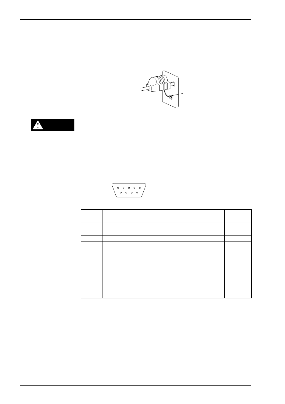
Connecting the AC power supply
Plug the BL-U1 power cable into the power receptacle. At the same time, ground
the frame ground wire.
Make sure that the power supply provides 100 to 240 VAC ± 10%.
1.2
Connecting the BL-U1 to a BL series
Use the READER port on the BL-U1.
The pin assignment is shown in the table below:
UL-U1 READER port pin assignment
FG line
CAUTION
2
1
3 4 5
6 7 8 9
D-sub 9-pin (male)
DCE specification (defined as modem)
#4-40 screw (female)
Pin No.
Symbol
Description
Signal
direction
1
TIM
Trigger input
Output
2
RD (RXD)
Send data through RS-232C
Output
3
SD (TXD)
Receive data through RS-232C
Input
4
OK
OK uotput
Input
5
GND (SG)
Ground (common ground for respective sig-
nals)
——
6
NG
NG uutput
Input
7
RS (RTS)
Enable to send data through RS-232C
(always ON)
Input
8
CS (CTS)
Request to send data through RS-232C
(control method can be selected by DIP
switches)
Output
9
+5V
+ 5VDC power supply
Output