System configuration, System configuration -2 – KEYENCE LK-CC100/DN100 User Manual
Page 8
1
1-2
1 Before Use
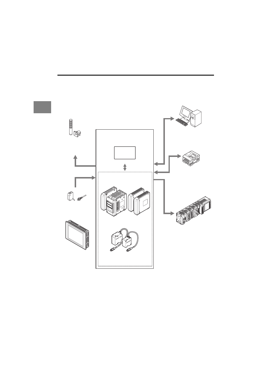
System Configuration
The LK-CC100 and LK-DN100 can be used along with commercially-available devices for
various purposes.
*1: The single unit type controller (LK-G5001V/LK-G5001PV) can be separated into the display panel
and controller unit. They can also be purchased separately.
The single unit type controller is labeled as LK-HD500 on the display panel side and as LK-G5001
or LK-G5001P on the terminal panel side.
*2: Refer to the LK-Navigator 2 User's Manual (the PDF file is on the CD-ROM) for further details on the
setup support software (LK-H2) LK-Navigator 2.
LK
-H
D500
OUT1
HI
GO
LO
TIM
OUT2
HI
GO
LO
TIM
HEAD
1
LASE
R ON
STAB
ILITY
BRIG
HT
DARK
HEAD
2
LASE
R ON
STAB
ILITY
BRIG
HT
DARK
ZER
O
ENT
SET
PRO
GRA
M
Programmable logic controller
(PLC)
Enables synchronization control
of the measurement and
program number switching as
well as reading of control output
and measured values.
Enables control and measured
value reading through RS-232C
communication or the parallel
I/O board of the PC.
Recorder
Records the measurement
result.
Indicator, buzzer
Issues an alarm depending
on the comparator result
output.
Photoelectric sensors,
proximity sensors
Use to send timing input signals
when the measurement object is
detected.
Dedicated touch panel
LK-HD1001
Head (12 heads max.)
LK Navigator2
Setup support software (LK-H2)
*2
LK-G5000 Series
USB/RS-232C/
Ethernet
Controller
*1
LK-G5001V/LK-G5001PV
Head expansion unit
LK-HA100
Expansion unit
LK-CC100
LK-DN100