KEYENCE LK-CC100/DN100 User Manual
Page 46
3-10
3
3 Connecting to DeviceNet
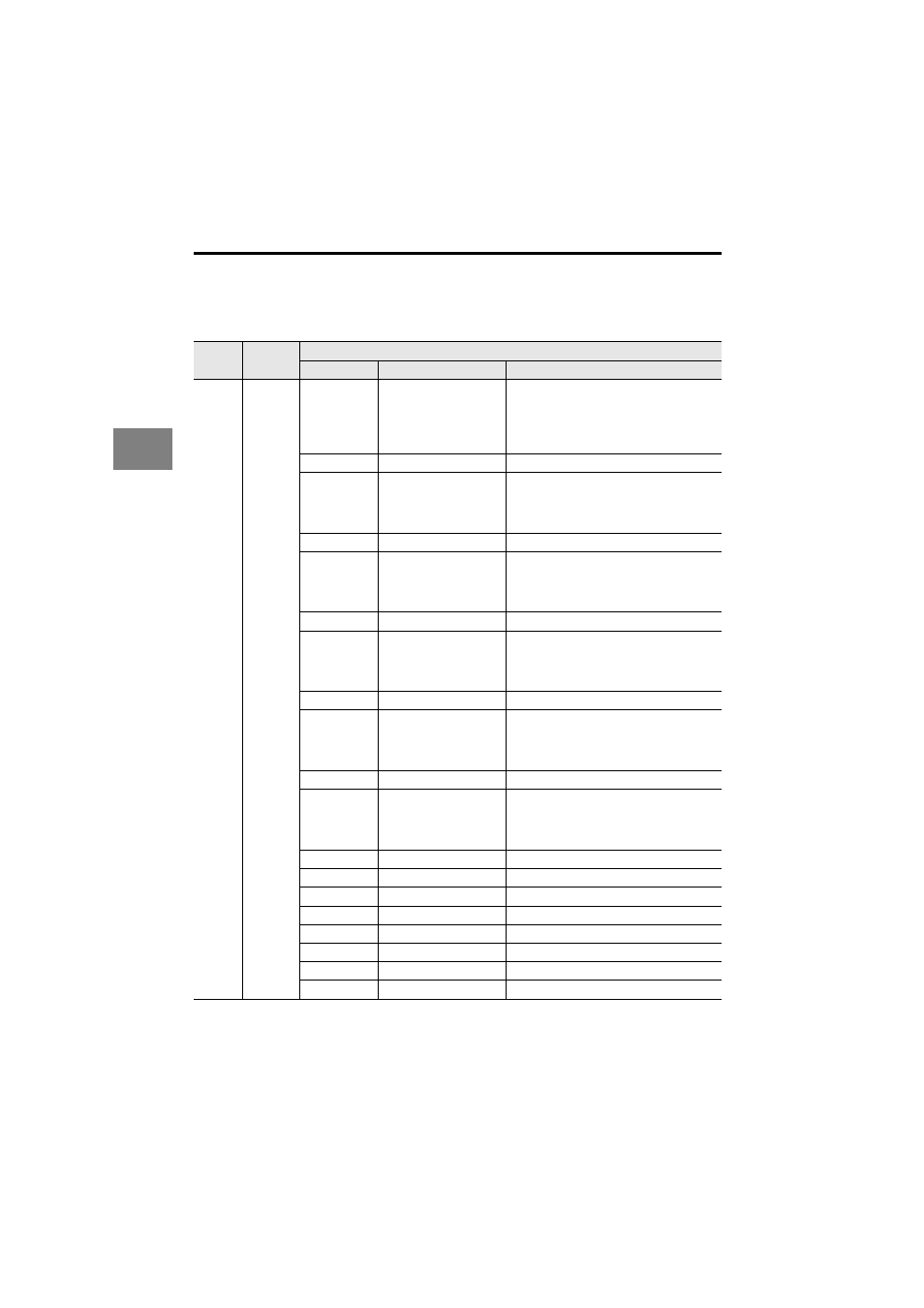
Output control buffer
The output control buffer refers to control signals sent from the DeviceNet master node to
the LK-DN100.
LK-
DN100
Signal
direction
DeviceNet master node
Offset
Signal name
Explanation
Read
control
buffer
Bit (0)
CHG_PRG_REQ
• Requests to change to the program
number stored in SET_PRG_NUM at the
rising edge from OFF (0)
ON (1).
• Ends the request at the falling edge from
ON (1)
OFF (0).
Bit (1)
System reserved
Bit (2)
SYNC_TIM_ON_REQ
• Requests synchronized timing ON at the
rising edge from OFF (0)
ON (1).
• Ends the request at the falling edge from
ON (1)
OFF (0).
Bit (3)
System reserved
Bit (4)
SYNC_TIM_OFF_REQ
• Requests synchronized timing OFF at
the rising edge from OFF (0)
ON (1).
• Ends the request at the falling edge from
ON (1)
OFF (0).
Bit (5)
System reserved
Bit (6)
SYNC_ZERO_ON_REQ
• Requests synchronized zero ON at the
rising edge from OFF (0)
ON (1).
• Ends the request at the falling edge from
ON (1)
OFF (0).
Bit (7)
System reserved
Bit (8)
SYNC_ZERO_OFF_REQ
• Requests synchronized zero OFF at the
rising edge from OFF (0)
ON (1).
• Ends the request at the falling edge from
ON (1)
OFF (0).
Bit (9)
System reserved
Bit (10)
SYNC_RESET_REQ
• Requests synchronized reset at the
rising edge from OFF (0)
ON (1).
• Ends the request at the falling edge from
ON (1)
OFF (0).
Bit (11)
System reserved
Bit (12)
System reserved
Bit (13)
System reserved
Bit (14)
System reserved
Bit (15)
System reserved
Bit (16*m+0)
System reserved
Bit (16*m+1)
System reserved
Bit (16*m+2)
System reserved