Mounting/connecting the units, Connecting the communication unit, Mounting/connecting the units -7 – KEYENCE LK-CC100/DN100 User Manual
Page 13: Connecting the communication unit -7
1-7
1
1 Before Use
Mounting/Connecting the Units
Connecting the communication unit
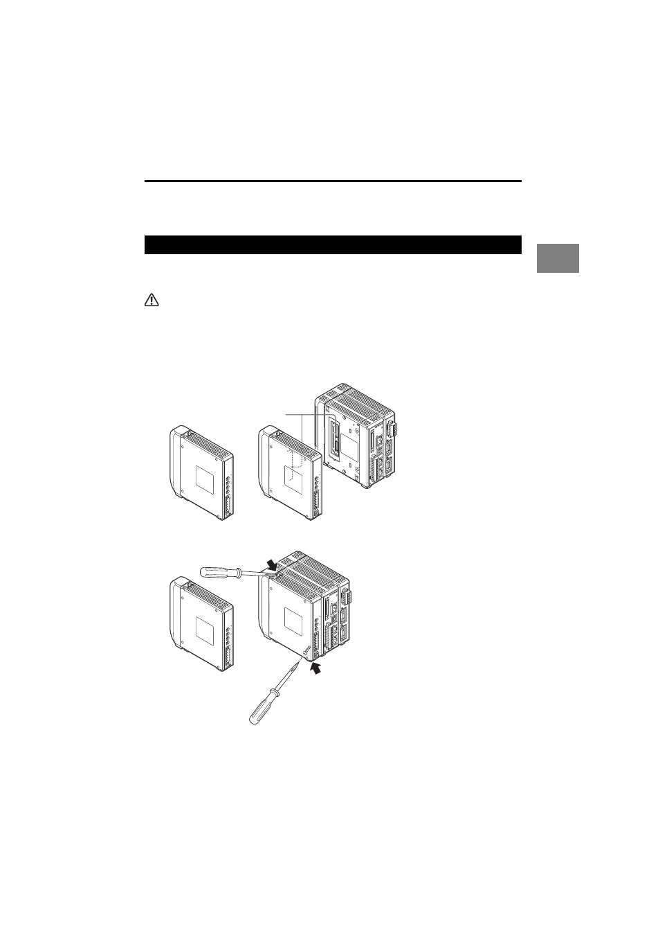
Connect the LK-CC100 CC-Link communication unit or the LK-DN100 DeviceNet
communication unit to the controller.
CAUTION
Turn off the power of the LK-G5000 Series before connecting the communication unit. Otherwise, you
may suffer a shock or damage the unit.
1
Connect the communication unit by aligning its connector to the connector on
the left side of the LK-G5000.
You need to remove the sticker attached to the left side of the LK-G5000 beforehand.
2
Secure the communication unit by tightening the two connecting screws.
Tightening torque
Limit the tightening torque to 0.7 Nm or less.
1
1
2
3
4
5
6
7
8
9
10
11
12
13
14
15
16
17
18
19
20
2
21
22
23
24
25
26
27
28
29
30
31
32
33
34
35
36
37
38
39
40
LASER ON
ETHERNET
USB
DISPL
AY
RS-232C
HEAD
1
(V)
(A)
0V
(V)
(A)
0V
COM IN
ZER
O 1
TIMING 1
GO
LASER 1
DC 24V
1
HEAD
LK
-G5000
2
MS
NS
10
(FG
)
LK-DN100
1
B R
ATE
V+
CAN H
SHIELD
CAN L
V-
ST
A
TION No.
L R
UN
SD
RD
L ERR
10
LK-CC100
1
B R
ATE
SLD
DG
DB
DA
MODE
ST
A
TION No.
(FG
)
LK-CC100
or
LK-DN100
Connector
1
1
2
3
4
5
6
7
8
9
10
11
12
13
14
15
16
17
18
19
20
2
21
22
23
24
25
26
27
28
29
30
31
32
33
34
35
36
37
38
39
40
LASER ON
ETHERNET
USB
DISPLA
Y
RS-232C
HEAD
1
(V)
(A)
0V
(V)
(A)
0V
COM IN
ZER
O 1
TIMING 1
GO
LASER 1
DC 24V
1
HEAD
LK
-G5000
2
MS
NS
10
(FG
)
LK-DN100
1
B R
ATE
V+
CAN H
SHIELD
CAN L
V-
ST
A
TION No.
L R
UN
SD
RD
L ERR
10
LK-CC100
1
B R
ATE
SLD
DG
DB
DA
MODE
ST
A
TION No.
(FG
)
Screw position
Screw position
LK-CC100
or
LK-DN100