2 device maps, Co mm u ni c a ting w ith t he fd -s s er ie s, Remote output ry (master station -> dl-cl1) – KEYENCE DL-CL1 User Manual
Page 33
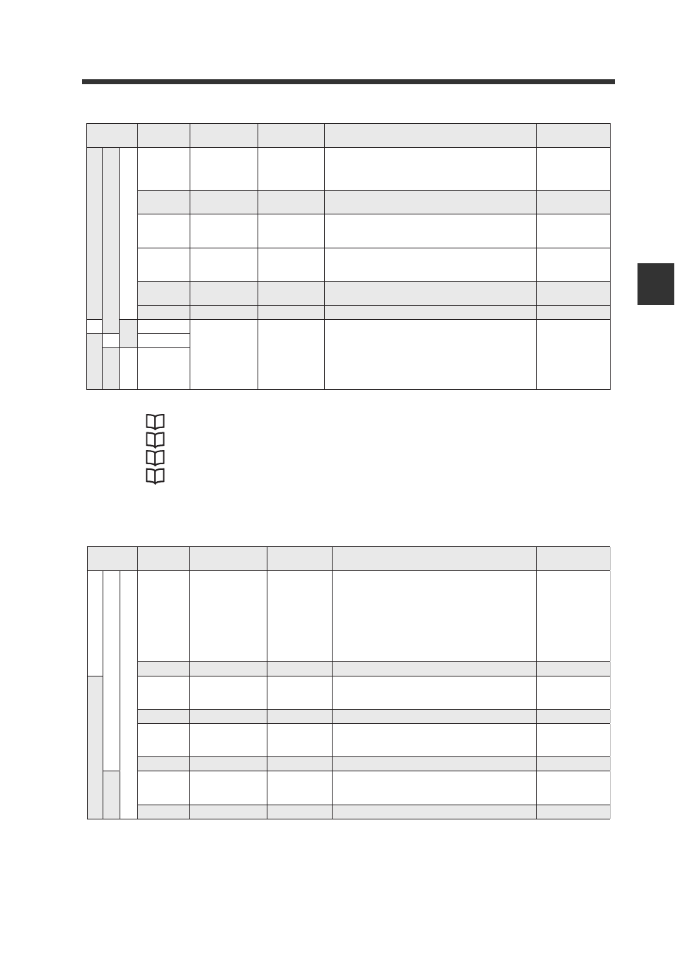
3-2 Device Maps
3-5
3
Co
mm
u
ni
c
a
ting
w
ith t
he FD
-S
s
er
ie
s
- CC-Link Compatible Network Unit DL-CL1 User’s Manual (FD-S) -
Number [n] denotes the first relay number assigned to the DL-CL1.
*1
See
"Reading an Output from a Sensor Amplifier" (page 3-17).
*2
See
"Reading Current Values (Instantaneous Flow Rate) from Sensor Amplifiers" (page 3-18).
*3
See
"Reading/Writing Settings or Status of a Sensor Amplifier" (page 3-21).
See
"Issuing a Motion Command to a Sensor Amplifier" (page 3-20).
Remote Output RY (Master Station -> DL-CL1)
Operating
mode
Device no.
(HEX)
Name
Communication
method
Description
Reading range
Monitor mode
1
RX[n] + 53
Current
Value Update
Locked
-
This is output when current value update is
locked (current value update lock request (RY[n]
+ 53) is enabled).
0: Update
enabled
1: Update
locked
RX[n] + 54
to 5D
System
reserved
-
Unusable
RX[n] + 5E
Current value
page change
complete
*2
Used for reading the current value.This is output
when the current value page has been changed.
0->1: Change
complete
RX[n] + 5F
Current value
page change
error
*2
Used for reading the current value.This is output
if an error occurs while changing the current
value page.
0:No Error
1:Error
RX[n] + 60
to 63
(Not used)
-
-
-
RX[n] + 6F (Not used)
-
-
-
RX[n] + 1B
Remote ready
-
This is output when the DL-CL1 is correctly
connected to the CC-Link system.
1: Proper communication is provided.Data from
the sensor amplifi er will be updated.
0: Proper communication is not provided.Data
from the sensor amplifi er will not be updated.
0: In preparation
1: Ready
RX[n] + 3B
RX[n] + 7B
Operating
mode
Device no.
(HEX)
Name
Communication
method
Description
Writing range
S
mall-memor
y mode
1
S
mall-memor
y mode
2
Monitor mode
1
RY[n] + 00
to 03
Integration reset
input
ID 01 to ID 04
*1
Receives integration reset input by assigning
each sensor amplifi er (ID 01 to ID 04) to each
RY.
0: OFF
1: ON
RY[n] + 0F System reserved
-
Unusable
RY[n] + 10
to 13
Flow rate hold
reset input
ID 01 to ID 04
*1
Receives fl ow rate hold reset input by
assigning each sensor amplifi er (ID 01 to ID
04) to each RY.
0: OFF
1: ON
RY[n] + 1F System reserved
-
Unusable
RY[n] + 20
to 23
Zero adjustment
input
ID 01 to ID 04
*1
Receives zero adjustment input by assigning
each sensor amplifi er (ID 01 to ID 04) to each
RY.
0: OFF
1: ON
RX[n] + 2F System reserved
-
Unusable
RY[n] + 30
to 33
Temperature
hold reset input
ID 01 to ID 04
*1
Receives temperature hold reset input by
assigning each sensor amplifi er (ID 01 to ID
04) to each RY.
0: OFF
1: ON
RX[n] + 3F
System reserved
-
Unusable