3 names and functions of each part, Names and functions of each part -4, Names and functions of each part – KEYENCE DL-CL1 User Manual
Page 14
1-4
1
Bef
o
re
U
s
in
g
- CC-Link Compatible Network Unit DL-CL1 User’s Manual (FD-S) -
1-3
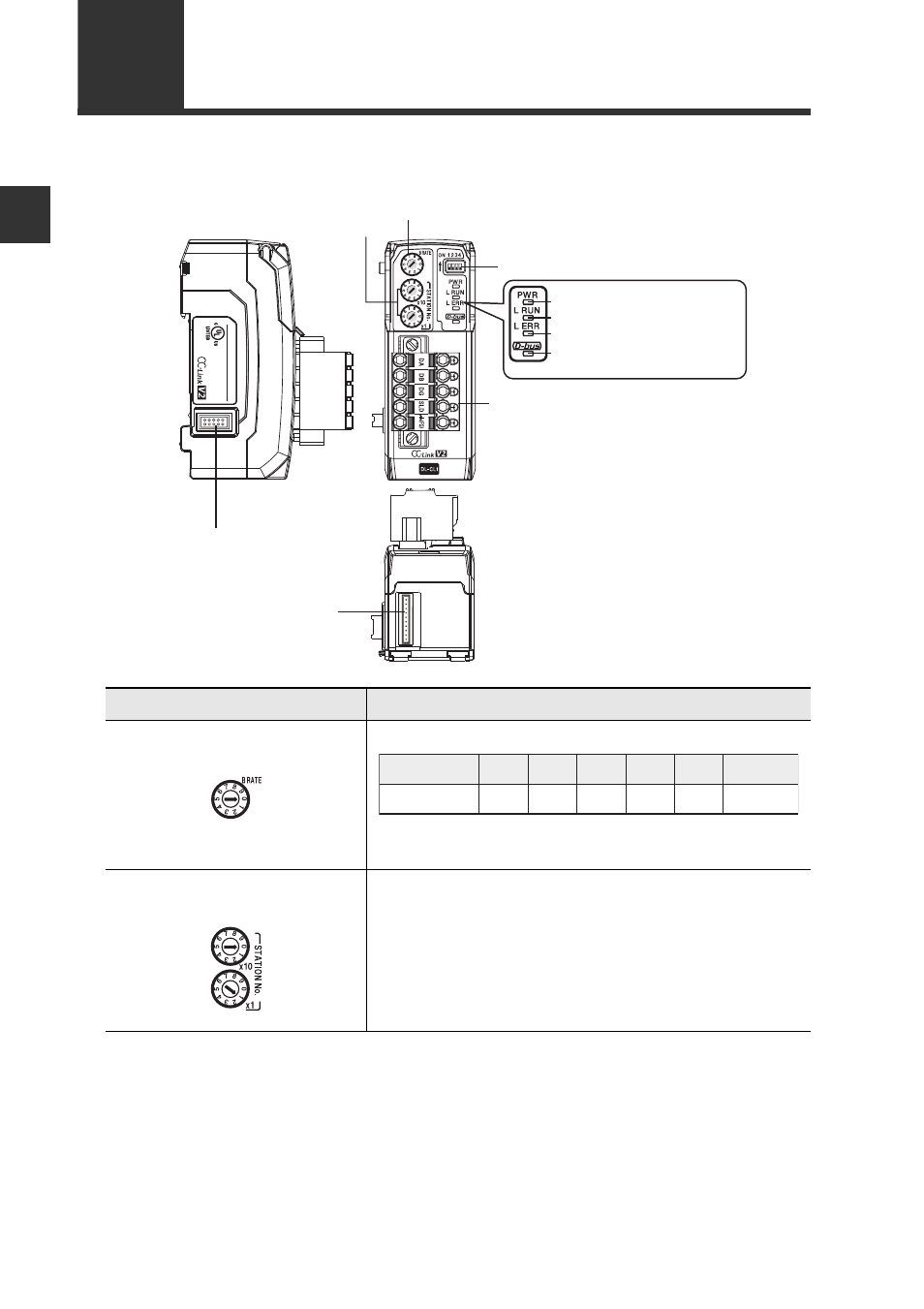
Names and Functions of Each Part
This section describes the part names and functions of the DL-CL1.
Name
Description
(1) Transmission rate setting
switch
Sets the transmission rate of CC-Link.
Default value: 0
(2) Station number setting
switch
Sets the station number of the DL-CL1 in the CC-
Link.
x10: Ten's digit
x1: One's digit
Setting range: 01 to 64
Default value: 01
(5)
Communication indicator (green)
(6) Communication error indicator (red)
(7) Sensor communication indicator
(red/green)
(4) Power indicator (green)
(9) Sensor amplifier connector
(for DIN rail mounting type)
(8) CC-Link connector
(1) Transmission rate setting switch
(3) Operating mode setting switch
(2) Station number setting switch
(10) Sensor amplifier connector
(for panel mounting type
and large display type)
DL
-CL1
20-30V DC, Class2
15JN
IND.CONT.EQ.
0
1
2
3
4
5 to 9
Transmission rate
(bps)
156k
625k
2.5M
5M
10M Cannot be set