KEYENCE DL-CL1 User Manual
Page 24
2-2 Wiring
2-8
- CC-Link Compatible Network Unit DL-CL1 User’s Manual (FD-S) -
2
Con
nect
io
n
a
nd
Co
nf
igu
ra
tio
n
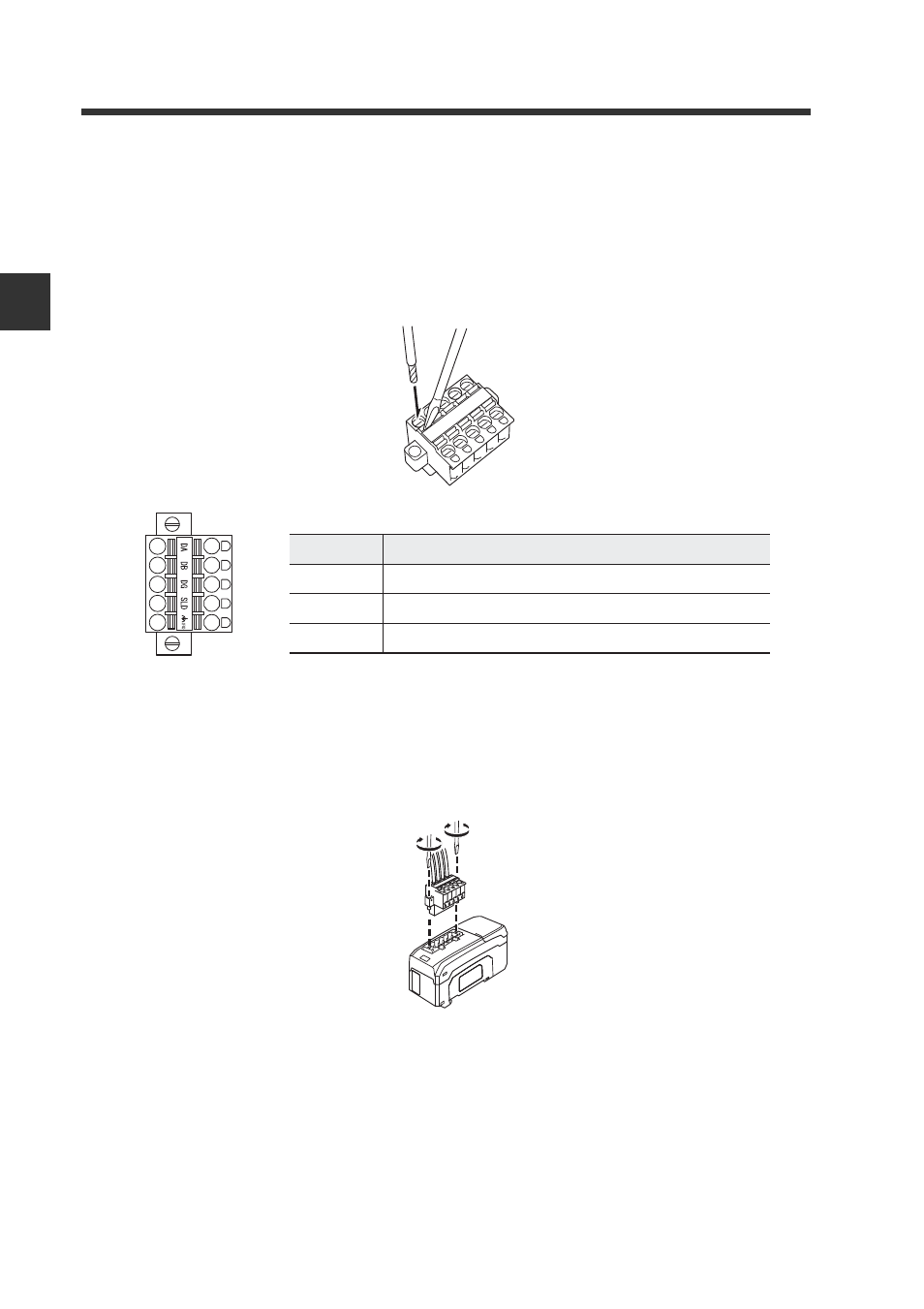
Connecting the cable
Use the following procedures to connect to the CC-Link connector supplied with the
DL-CL1.
1
Connect the trimmed cable to the CC-Link connector.
Insert the cable completely.
2
Attach the CC-Link connector to the DL-CL1.
Plug the connector into the DL-CL1 and screw it down with the screws on each
end.
(Tightening torque: 0.2 to 0.3 N•m)
Terminal name
Function
DA/DB/DG
Communication signal
SLD
Connect the shielded wire of the CC-Link cable.
FG
Ground this functional ground terminal. (Ground resistance: 100 ohm or less)
See also other documents in the category KEYENCE Sensors:
- LR-TB2000 Series (12 pages)
- LR-TB5000 Series (12 pages)
- LR-ZB250AN/AP (4 pages)
- LR-ZB250AN/P (3 pages)
- LR-ZBxN/P Series (3 pages)
- LR-ZBxxB (3 pages)
- OP-85135 (1 page)
- PZ-G Series (2 pages)
- PZ-V/M (2 pages)
- PS-N10 Series (12 pages)
- PX-10 (10 pages)
- CZ-V21A(P) (10 pages)
- CZ-K1(P) (8 pages)
- CZ-V1 (8 pages)
- FS-N10 Series (6 pages)
- FS-N10 Series (116 pages)
- FS-N15CN (1 page)
- FU-93(Z) (2 pages)
- FU-V Series (2 pages)
- FS-V30 (6 pages)
- FU-A40 (1 page)
- NU/FS-N Series (16 pages)
- FS-V33(P) (8 pages)
- FS-V21 (4 pages)
- FS-V22 (4 pages)
- FS-V11(P) (4 pages)
- FS-V1(P) (4 pages)
- LV-N10 Series (12 pages)
- LV-N10 Series (112 pages)
- LV-S62 (1 page)
- OP-84350 (1 page)
- LV-SA (10 pages)
- LV-SB (12 pages)
- OP-87305 (1 page)
- LV Series (10 pages)
- LV-B102 (1 page)
- EV-108M(U) (1 page)
- EZ Series (1 page)
- EM Series (1 page)
- ES-M1(P) (3 pages)
- EX-V Series (120 pages)
- EX-500(W) Series (16 pages)
- GV Series (10 pages)
- IA Series (8 pages)
- LB-1000(W) (24 pages)