KEYENCE DL-CL1 User Manual
Page 21
2-1 Installation and Connection to Sensor Amplifiers
2-5
2
C
onn
ec
tion
a
nd
C
onf
ig
u
ra
ti
o
n
- CC-Link Compatible Network Unit DL-CL1 User’s Manual (FD-S) -
3
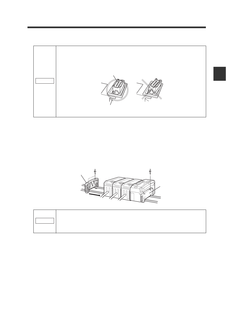
Mount the supplied end units (OP-26751: a set of two pieces) on the outer
side faces of the amplifier and the CC-Link compatible communication
unit DL-CL1. Then, fix the end units with the screws on the top of each
end unit (2 points x 2 units). (Tightening torque: 0.6 N•m or less)
Mount the end units in the same way as the CC-Link compatible communication
unit DL-CL1.
Make sure that the sensor amplifier connector (for DIN rail mounting
type) is not askew on the side face of the CC-Link compatible communi-
cation unit DL-CL1, as shown below. If the connector is askew, the DL-
CL1 may become damaged when connected to the sensor amplifier.
Press the CC-Link compatible communication unit DL-CL1 into full
engagement with the sensor amplifier. If the DL-CL1 is connected in
slant position or not pressed fully, it may be damaged when the power is
turned on.
NOTICE
Sensor amplifier connector
CC-Link compatible
communication unit DL-CL1
End unit
End unit
NOTICE