Power & relay board dip switch location -10 – Hardy HI 2151/30WC Single-Scale Controller User Manual
Page 64
HI 2151/30WC MANUAL
4-10
2. When the switch is OFF, Tare, Mode, Zero, and lb/kg keys are
available.
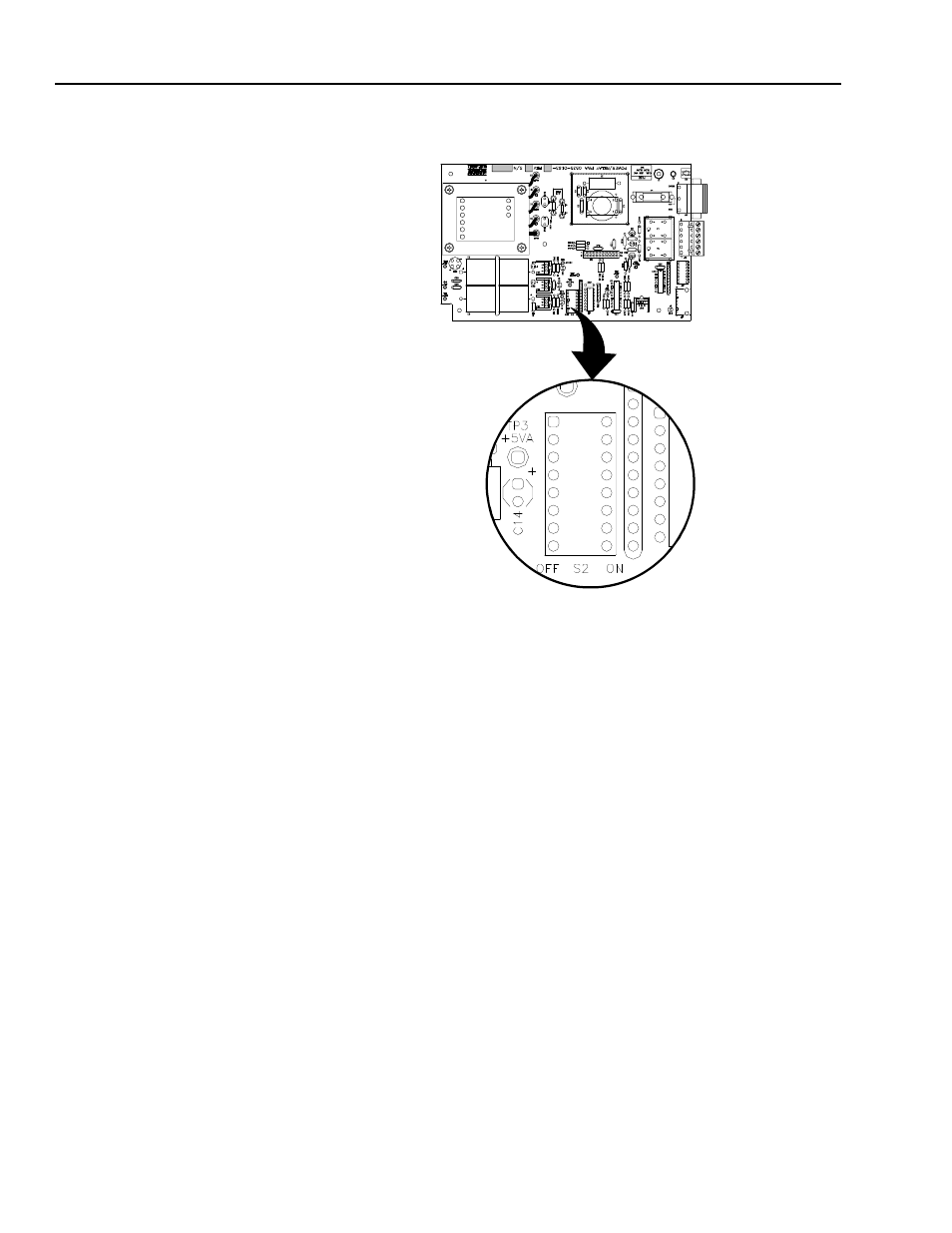
Configuring the Power &
Relay Board Dip Switches
S2 (See Fig. 4-12)
FIG. 4-12 POWER & RELAY BOARD DIP SWITCH LOCATION
1. When the switch is ON, incoming checksums are ignored. When
the switch is OFF incoming checksums are read.
2. S2-2 - When the switch is ON, the Peak Hold signal read is aver-
aged. When the switch is OFF, the Peak Hold signal is instanta-
neous.
3. S2-3 - When the switch is ON, the instrument is in the NBS mode
of operation. Resolution is limited to 1:10,000 counts. When the
switch is OFF, the resolution is 1:985,000.
4. S2-4 - This switch must be toggled (position changed) to enter NBS
calibration from the front panel CAL button.
5. S2-5 - Turns Off > character on print output serial port.
6. S2-6 - Puts unit in Blind Remote Mode.
7. S2-7 - is not used.
8. S2-8 - is used for resetting Calibration & Configuration to the Fac-
tory Defaults