Rs-422/485 configuration wiring -8, Wiring diagram serial communications -8 – Hardy HI 2151/30WC Single-Scale Controller User Manual
Page 106
HI 2151/30WC MANUAL
7-8
Additional Non-
standard
Transmission
Mode
•
Used most frequently. Only one "host" permitted.
•
Four wire RS-485 or multidrop RS-422 mode
•
When configured in four wire mode with the transmitter selectively
tri-stated, the board is operating in a four wire RS-485 or multidrop
RS-422 mode. This configuration doesn't meet either specification
but can be easier to program than either true specification.
RS-422/485
Wiring and
Electrical
Specifications
Serial communication signal configuration and wiring is dependent on
how the board is configured. The following notes are typical methods
of connection. It should be realized that these methods vary and are
only furnished to offer a starting point for configuration:
•
Signal Grounds
A direct connection between signal grounds of the different
devices is not desirable, rather a connection with approxi-
mately 100 ohms of resistance is recommended. Signal
ground should NOT be used as a shield.
•
Earth Ground Cable Shield
Typically, cable shields are tied to the ("frame") ground at
the end that is the best earth ground.
Pick up frame ground on the HI 2151/30WC with the phil-
lips head screw on the rear of the instrument labeled Shield.
•
Cable Type
The Tx+/Tx- and Rx+/Rx- wires are twisted pair (with outer
shield).
•
Serial Connector
Each function is wired to two pins to allow only one wire to
be put in each terminal position. (The same electrical signal
is routed to pins one and two on the board.)
RS-422/485
Configuration
Wiring
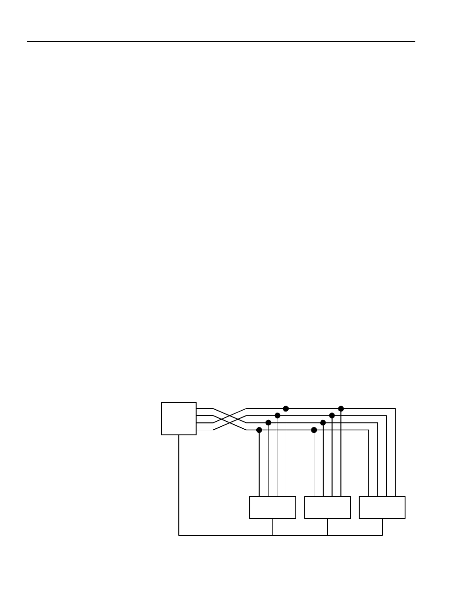
FIG. 7-4 WIRING DIAGRAM SERIAL COMMUNICATIONS
HOST
DEVICE
HI 2151
HI 2151
HI 2151
+TXD
-TXD
+RXD
-RXD
-R
X
D
+R
X
D
+T
X
D
-T
X
D
-R
X
D
+R
X
D
+T
X
D
-T
X
D
-R
X
D
+R
X
D
+T
X
D
-T
X
D
GN
D
SI
G
GN
D
SI
G
GN
D
SI
G
GN
D
SI
G