About the analog output card option -4, Setting the jumpers -4, Terminating controller, all dip switches set – Hardy HI 2151/30WC Single-Scale Controller User Manual
Page 58
HI 2151/30WC MANUAL
4-4
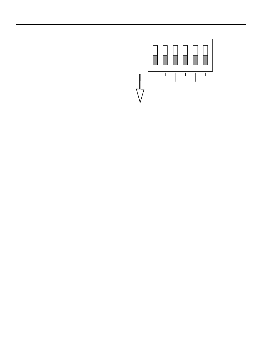
FIG. 4-5 TERMINATING CONTROLLER, ALL DIP SWITCHES
SET IN THE ON POSITION
Step 9.
Replace the option board.
Step 10. Gently slide the rear panel back into the extrusion
Step 11. Replace the four pan-head machine screws that fasten the rear
panel to the extrusion.
Step 12. Connect the power cord.
Analog Output Option
Card Configuration
Procedures -B1
About the Analog
Output Card Option
The analog transmitter outputs to a receiving device (PLC, Computer
etc.). The transmitter outputs a user selectable Gross, Net, Rate of
Change (ROC), Peak or Total Weight as 0-5V, 0-10V, 0-20mA, or 4-
20mA (via the front panel you can reverse the voltage and current
ranges, See Chapter 5 for procedures). When configuring the Analog
Output Card, both the receiver and the HI 2151\30WC must be in
the same mode (e.g. Gross, Net, Rate of Change (ROC) Peak or
Total Weight). The analog card can also span the voltage or milliamp
ranges over a portion of the weight data. The outputs are electrically
and optically isolated from the main board. The Analog Output Card is
adjusted at the factory. (See Chapter 5, Section 5.6 for Setup Instruc-
tions)
Setting the Jumpers
Disassembling the
rear panel and
setting jumpers
Step 1.
Repeat steps 1-4 above. (See Fig. 4-2)
Step 2.
Set the jumper that matches the system's feedback voltage or
current configuration. (See Table 4-1)
1
2
3
4
5
6
O
N