Output option board installation procedures -15, Load cell connection (non c2 load cells) j1 -14, Output option board installation procedures – Hardy HI 2151/30WC Single-Scale Controller User Manual
Page 44
HI 2151/30WC MANUAL
3-14
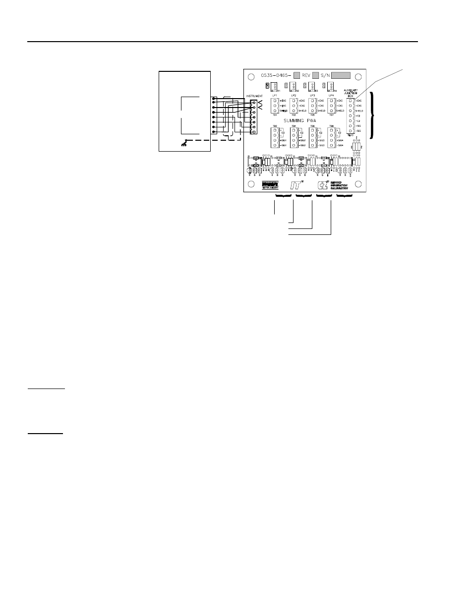
FIG. 3-10 LOAD CELL CONNECTION (NON C2 LOAD CELLS) J1
NOTE:
Contact Hardy Customer Support for installation information when using an external
power supply.
NOTE:
The Auxiliary Junction Box connector is an optional item and must be ordered from
the factory.
NOTE:
Record all load cell serial numbers and location on the label located on the inside
cover of the junction box.
Output Option Board
Installation Procedures
WARNING
DANGEROUS VOLTAGE IS PRESENT WITHIN THE ENCLOSURE OF
THE INSTRUMENT AND PRESENTS A RISK OF ELECTRICAL SHOCK.
ALWAYS UNPLUG THE POWER CORD BEFORE OPENING AND SERVIC-
ING THE INSTRUMENT.
CAUTION
INSTALLATION AND SERVICING OF THIS UNIT SHOULD BE PER-
FORMED BY AUTHORIZED AND QUALIFIED SERVICE PERSONNEL
ONLY. FOLLOW ALL ELECTROSTATIC DISCHARGE (ESD) PROCE-
DURES WHEN OPENING THE INSTRUMENT.
Step 1.
Disconnect the power cord.
Step 2.
Detach all interconnect cabling.
Step 3.
Use a phillips screw driver and remove the four pan head
machine screws that fasten the rear panel to the extrusion.
Step 4.
Gently pull out the rear panel with the printed circuit boards
attached. The main board is in clear view
Step 5.
Remove the appropriate option cover from the rear panel
(Option 1 or Option 2 cover) as required. Option 1 cover has
LOAD CELL 1
LOAD CELL 2
LOAC CELL 3
LOAD CELL 4
TO AUXILLARY
JUNCTION BOX
FOR 5 OR MORE
LOAD CELLS
OR 5TH LOAD CELL
WEIGHT
CONTROLLER
C2
-
+
-EXC
-SEN
-SIG
+SIG
+SEN
+EXC
LOAD
CELL
CONNECTOR
+EXC
+SEN
-EXC
-SEN
SHIELD
N/C
N/C
+SIG
-SIG
TB9
SHIELD
-
+
J1
1
8
Opti onal
C2
C2
C2