Hardy HI 2151/30WC Single-Scale Controller User Manual
Page 49
Chapter 3 - Installation
3-19
FIG. 3-14 BCD QUAD TERMINATION BOARD OPTION
Step 1.
Locate a clear, flat mounting area within five feet of all HI
2151/30WCs.
Step 2.
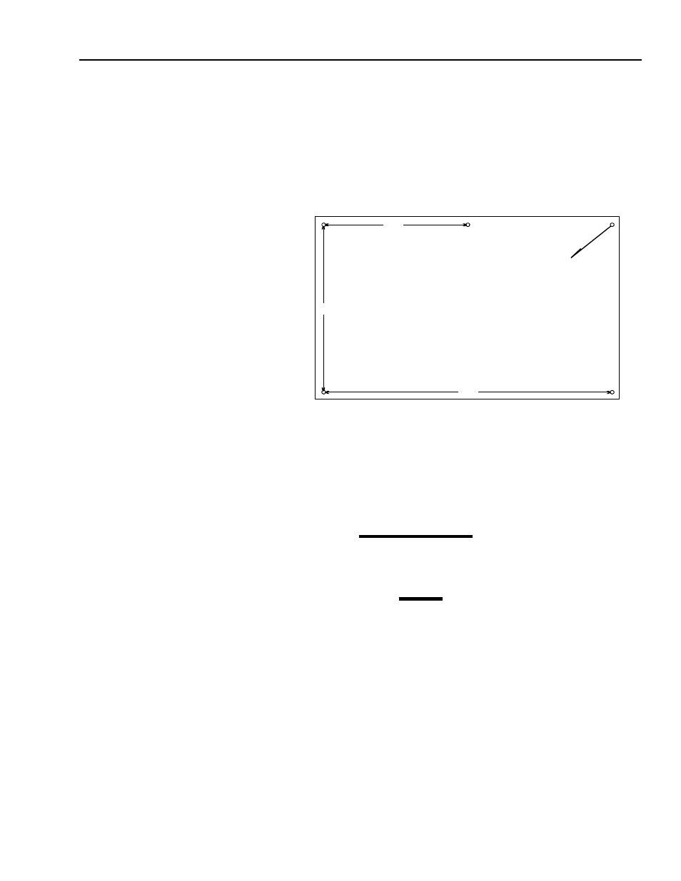
Use the measurements shown in Figure 3-15 BCD Termina-
tion Board Installation Drill Template Illustration or P/N
0596-0117 drill template to mark five mounting holes. (See
Fig. 3-15)
FIG. 3-15 BCD TERMINATION BOARD INSTALLATION DRILL
TEMPLATE
Step 3.
Drill 3/16-inch holes where marked.
Step 4.
Install five P/N 2815-0053 standoffs in the holes.
Step 5.
Install BCD terminal board on standoffs.
Step 6.
Connect P/N 0509-0389-01 ribbon cables between the BCD
output (instrument option slot 2) of up to four HI 2151/
30WCs and BCD terminal board jacks J1 through J4.Connect
control lines from computer to TB1.
Step 7.
For installations with more than four HI 2151/30WCs, pro-
ceed as follows:
Step 8.
Install a second BCD terminal board within two feet of
installed BCD terminal board. Refer to steps 1 through 7.
Step 9.
Connect P/N 0509-0389-02 ribbon cable from J5 on one BCD
terminal board to J5 on the other BCD terminal board.
Step 10. Connect data/status lines from BCD terminal board to com-
puter. (See Fig. 3-16)
•
Wire Size: 26 AWG to 20 AWG
4.50"
3.62"
7.25"
Dia .1875
5 places