Chapter 3 - installation, Fig. 3-19, Installation details – Hardy HI 2151/30WC Single-Scale Controller User Manual
Page 53: Fig. 3-20 standoff assembly
Chapter 3 - Installation
3-23
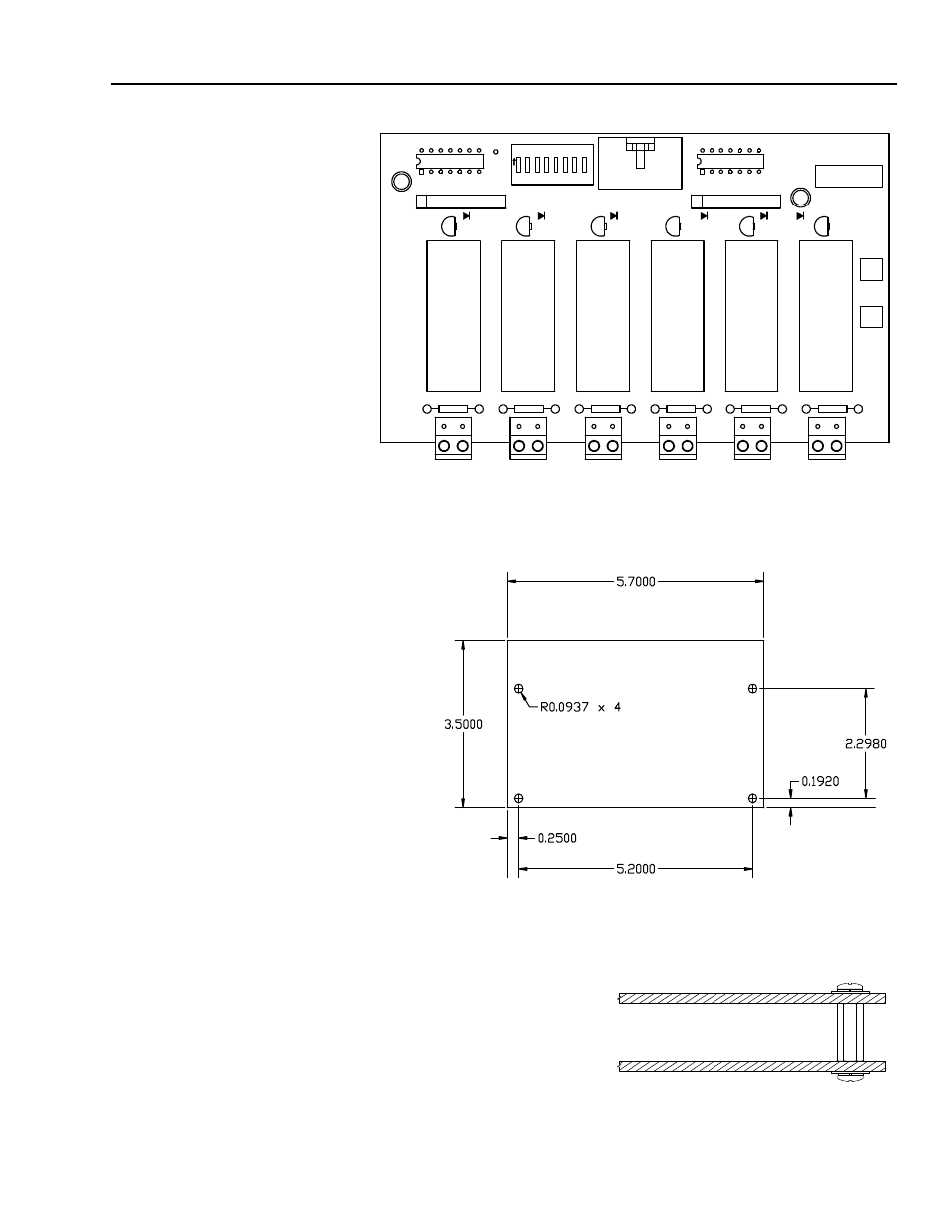
FIG. 3-18 SET POINT RELAY OPTION BOARD
Step 1.
Use the measurements shown in HI 2151/30WC Installation-
Details (See Fig. 3-19) to make four mounting holes.
FIG. 3-19
INSTALLATION DETAILS
Step 2.
Drill 3/16-inch diameter holes where marked. (See Fig. 3-19)
Step 3.
Install four P/N 2815-
0063 standoffs in the
drilled holes.
Step 4.
Install the relay
option board on the
standoffs. (Fig. 3-20)
FIG. 3-20 STANDOFF ASSEMBLY
U1
RN1
TP 1
+ 5V 1
N.O.
N.O.
O
N
S
P
3
S
P
4
S
P
5
S
P
6
S
P
7
S
P
8
1 2
3
4
5
6
7
8
1
2
3
4
5 6
7
8
U2
PWA-RELAY,
HI2151/30WC
S/N -
TP2 GND
J1
S1
RN2
1
DS3
DS4
DS5
DS6
DS7
DS8
K3
K4
K5
K6
K7
K8
F3 5A
F4 5A
F5 5A
F6 5A
F7 5A
F8 5A
0
5
3
5
-0
3
5
7
R
E
V
-
J3
J4
J5
J6
J7
J8
1
2