Hardy HI 2151/30WC Single-Scale Controller User Manual
Page 132
HI 2151/30WC MANUAL
8-12
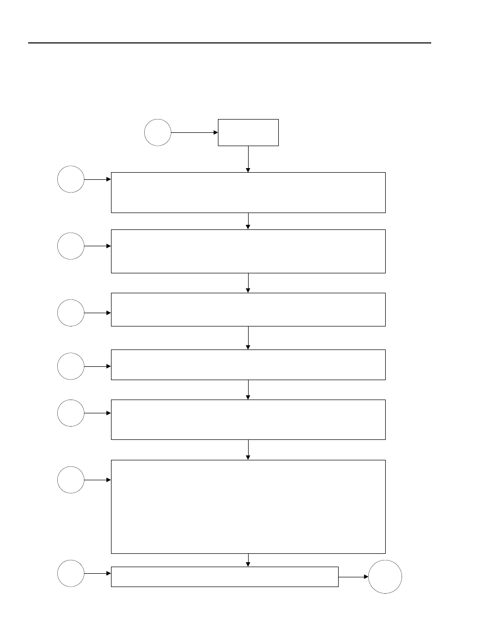
B1 - Guidelines for
Instabilities on
Formerly Operating
Systems (Cont'd)
Electrical
B1
Physical Grounding -
All common equipment share a common ground point.
Keep the ground cable length to earth ground as short as possible.
Install a new ground rod if the cable length is excessive.
Cable -
Cuts or breaks in the loadcell cable insulation allow moisture to wick into the
cable and loadpoints. This can setup stray capacitance charges and allow
ground currents to exist. This could create a highly intermittent situation.
Loadcells -
Ground straps must be installed to provide a direct discharge path to ground
around the loadpoints.
Vessel, Fill and discharge piping -
Ground all to a common point to eliminate electrical differences in potential,
and static build-up.
Cable Routing -
Seperate high voltage sources and cables from low voltage signal cables.
Stay a minimum of 14 inches from Magnetic fields and SCR controls.
Avoid parallel high voltage and signal cable runs.
Cable Shielding -
Ground low voltage cable shields only at the controller end.
Grounding both cable ends will produce ground currents.
Verify, with an ohm meter, the shield is only grounded at the weight controller.
Disconnect the shield at the controller and check for an open circuit between ground
and shield. Reconnect the shield to ground and confirm a proper ground path from
the I.T. Junction box to the controller.
Verify the shield is not connect to ground at the I.T. Junction Box.
Loadcell cable shields only pass thru the I.T. Junction Boxes and are not connected
to ground at that point.
Weight Controller - Common AC ground and Chassis grounds.
B1.1
B1.3
B1.2
B1.4
B1.5
B1.6
B1.7
GOTO
B