4 x 2 drive system - (steel bed) – Cub Cadet 4 x 2 Big Country - Poly Bed & Steel Bed User Manual
Page 81
4 X 2 Drive System - (Steel Bed)
77
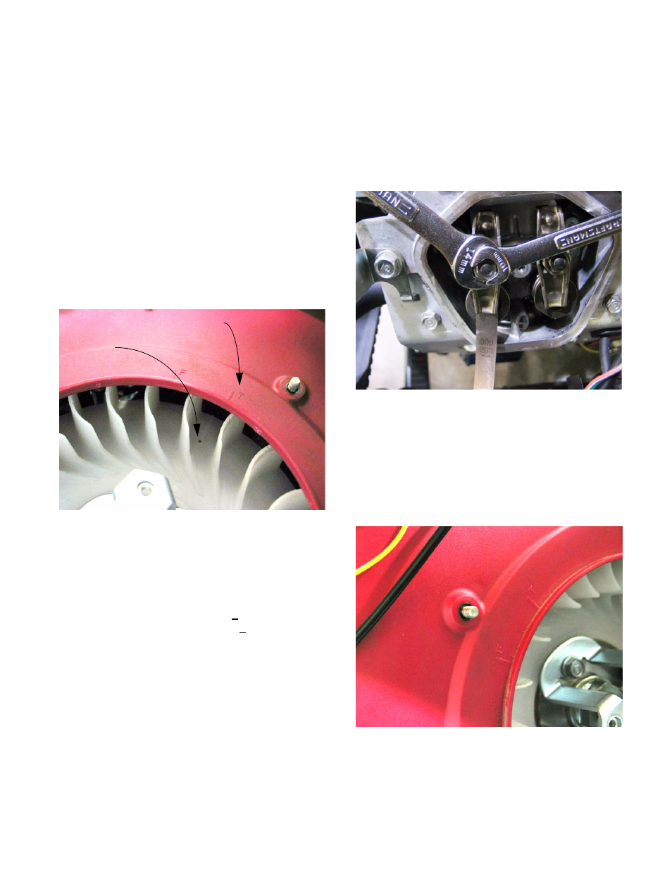
15.18.Rotate the engine crankshaft manually to locate
top dead center (TDC) on the compression
stroke for cylinder #1 (front cylinder).
See Figure 15.18.
•
Rotating the crankshaft clockwise (seen from the
fan side of the engine) will produce a puff of air
from the spark plug hole just before this point.
•
TDC on the compression stroke can be con-
firmed by the valves being closed.
•
There are timing marks on the fan cover that can
be seen if the finger guard and grid screen are
removed using a 10 mm wrench.
•
Cylinder #1 “T” mark is at the upper right hand
side of the fan cover. The mark on the fan
should align with it at TDC compression #1.
15.19.Check the clearance between the intake valve
and the rocker arm that acts on it. Check the
clearance between the exhaust valve and the
rocker arm that acts on it.
•
Intake valve clearance: 0.15 + 0.02mm (.006”)
Exhaust valve clearance: 0.20 + 0.02mm (.008”)
Figure 15.18
“T” Mark
Timing mark
on fan
15.20.If adjustment is necessary, hold the adjusting nut
with a 14mm wrench, and loosen the jam nut
with a 10mm wrench. Tighten the adjusting nut
until slight drag is felt on the feeler gauge.
Tighten the jam nut against the adjusting nut to
secure it. Double-check the adjustment to make
sure it did not slip during tightening.
See Figure 15.20.
15.21.Install the valve cover.
15.22.Rotate the crankshaft 270 degrees clockwise to
bring cylinder #2 to TDC position on the com-
pression stroke. The mark on the plastic fan
should align with the upper left “T” mark on the
fan cover. See Figure 15.22.
Figure 15.20
Figure 15.22