Poly bed 4 x 2 drive system – Cub Cadet 4 x 2 Big Country - Poly Bed & Steel Bed User Manual
Page 21
Poly Bed 4 X 2 Drive System
17
5.35. As the driving pulley compresses the belt, it is
forced outward in the tapered sheave.
NOTE: As the effective diameter of the driving
pulley increases, the belt is drawn deeper into
the sheave of the spring loaded driven pulley,
reducing its effective diameter. The combined
effect changes the drive ratio as speed goes up.
NOTE: Because the outer sheave of the driving
pulley is fully extended by around 3,300 RPM,
any vehicle speed increase beyond 3,300 RPM
engine speed is due directly to increases in
engine RPM, not to shifts in the effective drive
ratio.
5.36. If the vehicle fails to reach full speed (20 MPH)
or has lost performance, and the belt is good,
confirm that the engine still achieves it’s speci-
fied top-no-load speed and that the CVT
responds accordingly.
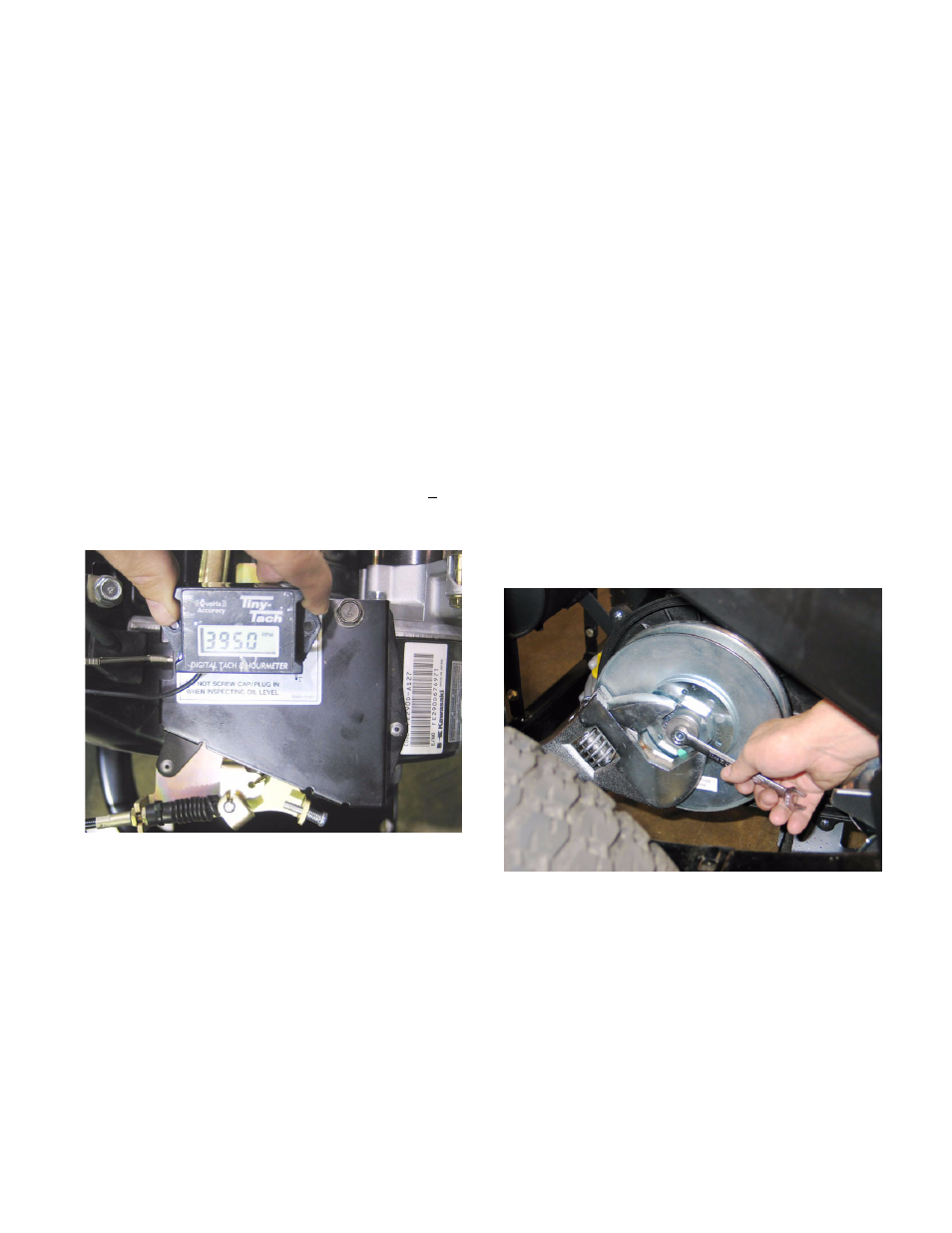
5.37. Top-no-load engine speed should be 4,000 + 50
RPM. Confirm this with a tachometer.
See Figure 5.37.
NOTE: The governor cover is riveted to the con-
trol plate. It is not adjustable.
5.38. If the engine fails to reach the specified top no-
load speed, or lacks performance under a light
load, check engine performance factors as
described in the Engine section of this manual:
•
Ignition function and spark plug condition.
•
Fuel system condition (fuel pump and lines, fuel
filter, air filter, carburetor, linkages).
•
Engine mechanical condition (valve lash adjust-
ment, cylinder compression, cylinder leakdown).
Figure 5.37
CVT Removal: Belt and Pulleys
5.39. Remove the exhaust pipe and CVT cover as
described previously in this section.
NOTE: If the belt is to be removed, but the pul-
leys are to be left in-place, it is not necessary to
remove the exhaust pipe. The CVT cover can
be moved aside, and the belt slipped-out. The
CVT cover does not need to be completely
removed to change a belt.
5.40. Disconnect and ground the spark plug H.T. lead.
5.41. If the pulleys are to be removed, loosen the bolts
that hold the pulleys to their respective shafts
before removing the belt.
NOTE: The bolts securing both CVT pulleys are
left hand thread. Turn them clockwise to
loosen them.
5.42. The driven pulley on the input shaft of the tran-
saxle can be removed using a 12 mm wrench.
Use an adjustable face pin spanner with reach of
at least 3” (7.62 cm) and a 1/4” (6 cm) pin size
(Snap-On stock number AFS483 is suitable) to
keep the pulley from rotating. See Figure 5.42.
•
Setting the parking brake will also help.
•
If no other means are available, the pulley can
be held with a 2” (50 mm) wrench on the large
nut.
5.43. The bolt holding the driving pulley to the engine
crankshaft can be loosened using a 14 mm
wrench.
Figure 5.42