Transaxle orientation, 4 x 2 drive system - (steel bed) – Cub Cadet 4 x 2 Big Country - Poly Bed & Steel Bed User Manual
Page 65
4 X 2 Drive System - (Steel Bed)
61
10.
TRANSAXLE ORIENTATION
10.1. The transaxle is a Dana / Spicer model H12
FNR. Before disassembly, become familiar with
and match-mark the components to establish
orientations for assembly.
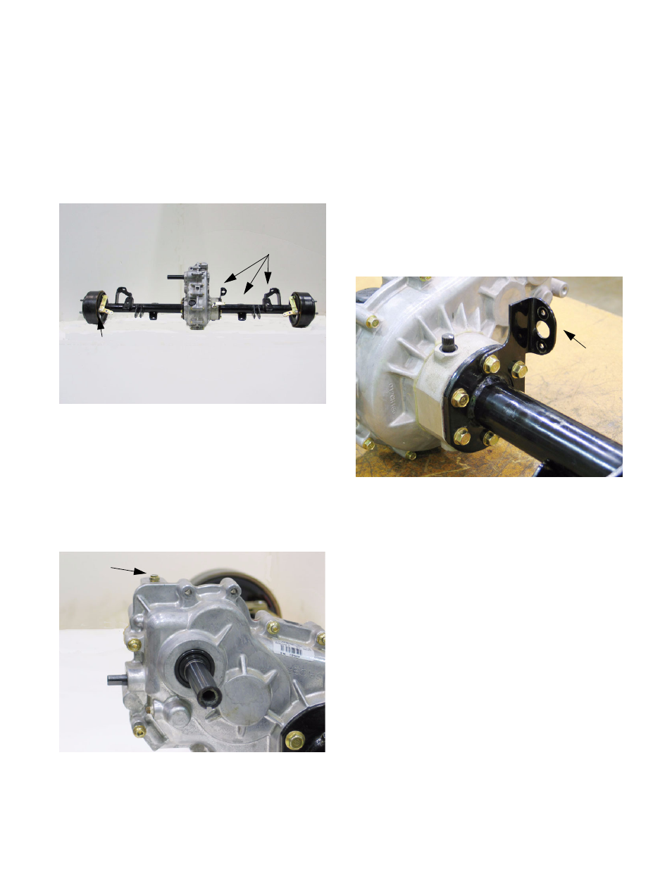
10.2. This is a bench procedure. For any internal
repairs, the transaxle must be removed from the
vehicle. See Figure 10.2.
10.3. Viewing the transaxle as it would be oriented in
the utility vehicle, with the input shaft to the left
hand side and the black rubber fill / check plug
facing up, directly above the axle tubes:
10.4. The vent valve is on the top of the right-side
housing. Remove it using a 7/16” wrench.
See Figure 10.4.
Figure 10.2
Front
Rear
Brake Clevis
Brackets
Figure 10.4
Vent
10.5. The top two holes for the bolts that connect the
left and right halves of the housing will be
vacant. The bracket that supports the vacuum
reservoir, the F-N-R actuator, and the neutral
switch is secured to these points. The bracket is
also bolted to two mounting bosses on the front
of the right side housing.
10.6. If not previously removed, take-off the bracket
for the differential lock actuator using a 9/16”
wrench. It is held by the same bolts that hold the
right side axle tube and differential lock housing
to the transmission housing. The mounting
flange on the bracket should be vertical, toward
the front of the transaxle. See Figure 10.6.
10.7. If not previously removed, the differential lock
lever should be parallel to the axle tubes, with
the clamp bolt to the rear when the differential
lock is engaged (lever pulled forward). It may be
necessary to rotate one of the axle shafts while
applying light forward force to the lever to
engage the differential lock. The lever is easily
removed using a pair of 7/16” wrenches.
10.8. The axle tubes are oriented so that the brake
actuators are at the top, and the brake cable
brackets extend toward the front of the vehicle.
The flats on the mounting flanges at the inboard
end of both axle tubes align with the flats on the
housing.
NOTE: The left side axle is roughly 1 3/4”
shorter than the right (differential lock) side.
NOTE: The axle bearings are greased, with
sealed bearings at each end. They are not lubri-
cated by the oil within the housing.
Figure 10.6
Differential
Lock
Bracket