4 x 2 drive system - (steel bed) – Cub Cadet 4 x 2 Big Country - Poly Bed & Steel Bed User Manual
Page 77
4 X 2 Drive System - (Steel Bed)
73
14.16.Clean the axle, apply a small amount of motor oil
or wheel bearing grease to the surface that the
axle bearing outer seal rides on, and install a
new seal onto the axle. The side of the seal with
the embossed words “THIS SIDE OUT” should
face the wheel flange.
14.17.Position the brake bracket assembly, then the
dust cover assembly on the axle. The dust
cover will not fit inside-out.
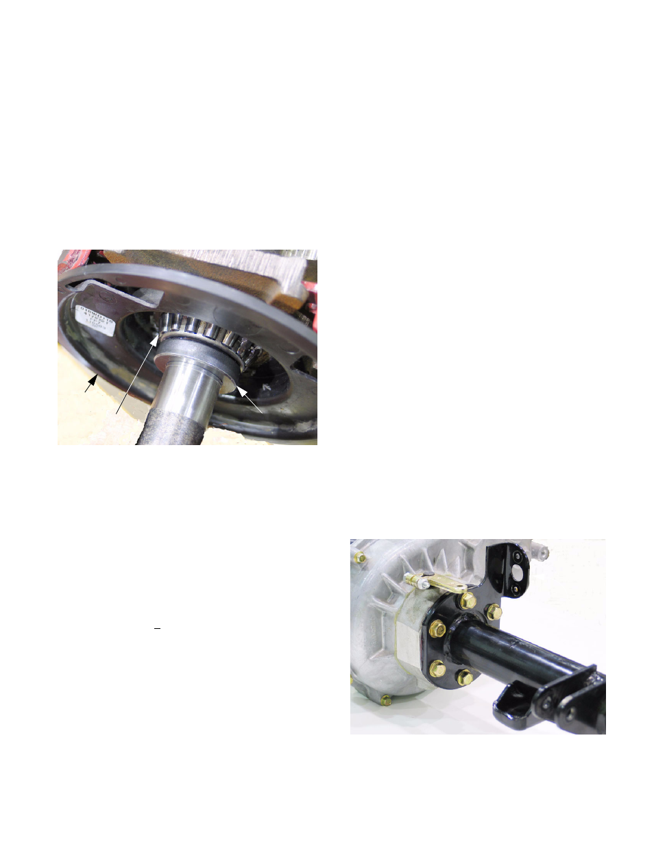
14.18.Pack the bearing with good quality wheel bear-
ing grease, and install the bearing on the axle.
See Figure 14.18.
14.19.Press the retaining ring onto the shoulder that
the axle bearing seats on, so that it holds the
axle bearing snugly in place.
14.20.Lubricate the finished surface near the retaining
ring with motor oil or gear lube.
14.21.Insert the axle into the axle tube.
14.22.Secure the brake bracket assembly and the dust
cover assembly to the axle using the four socket
head cap screws and nuts. Tighten them to a
torque of 200 + 20 in.-lbs. using a 1/2” wrench.
Figure 14.18
Dust cover
Bearing
Retaining ring
NOTE: To orient the brake bracket assembly to
the axle tube and dust cover:
•
The flats on the inner axle tube mounting flange
face front and rear.
•
The cable bracket extends forward of the axle
tube.
•
The large flat bosses that the top of the brake
shoes contact goes to the top.
•
The rectangular holes in the dust cover should
be near the flat bosses, for the brake actuator
arm to fit through.
•
The right side axle tube is shorter than the left
one, to accommodate the differential lock hous-
ing.
•
The right side axle shaft has two lengths of
splines separated by about 1 1/2” of shaft.
14.23.When assembling the axle tubes to the housing:
See Figure 14.23.
•
Thoroughly clean all traces of old sealant and
lubricants from the mating surfaces.
•
Apply a bead of non-silicone based sealant such
as Loctite 518 to the mating surfaces.
•
Install each axle tube, and secure them using
the six bolts previously removed.
•
The three top/front bolts on the right side axle
tube secure the differential lock actuator bracket.
•
Tighten the bolts to a torque of 25 to 35 ft.-lbs.
using a 9/16” socket.
Figure 14.23
Differential lock
actuator bracket