Poly bed 4 x 2 drive system – Cub Cadet 4 x 2 Big Country - Poly Bed & Steel Bed User Manual
Page 11
Poly Bed 4 X 2 Drive System
7
Differential Lock Control
In normal operation, a differential allows the two rear
wheels to rotate at different speeds. In a turning
maneuver, the wheels toward the outside of the turn
follow a path that describes a greater circumference
than the wheels toward the inside of the turn. Because
the outside wheels must turn faster than the inside
wheels, a differential is necessary.
Because it allows the rear wheels to rotate at different
speeds, a standard differential can only provide drive to
one wheel. One method of getting more traction is to
provide a manual device that over-rides the differential
feature by locking the two sides of the differential
together, providing drive to both rear wheels at the
same time.
It is not desirable to lock the differential together all the
time because it limits the turning radius of the vehicle:
•
The two wheels driving at the same speed tend
to want to push the vehicle straight ahead.
•
When the vehicle does turn, the two rear wheels
will fight against each-other for traction. In the
process they will apply exaggerated loads to the
drive train.
4.28. In normal use:
•
The differential lock should engage when the dif-
ferential lock lever is pulled-up.
•
There are five engagement dogs on the differen-
tial. The rear wheels must rotate at most 72
degrees relative to one-another before the
engagement dogs align, allowing them to lock
together.
•
Pulling-up on the differential lock lever extends
the spring at the front of the differential lock con-
trol cable. The spring applies force to the cable
and the differential lock lever on the transaxle.
When the engagement dogs align, the spring
force will push them into engagement.
•
Once engaged, the lever may be released, and
the differential will remain locked until the drive
load on the left and right wheels is equalized.
•
When the drive load between the rear wheels is
equalized, the load on the differential lock dogs
is relieved. When the load is relieved, torsion
spring on the differential lock lever will over-
come the friction between the differential lock
dogs, and cause them to disengage.
4.29. If the Big Country vehicle exhibits symptoms
indicating that the differential lock is not engag-
ing or disengaging properly, investigation should
begin with the control cable.
4.30. The differential lock control lever pivots on a
large clevis pin. The clevis pin is secured to the
frame by a hairpin clip.
4.31. The spring on the end of the differential lock con-
trol cable connects to one arm of the differential
lock control lever, and a return spring connects
to the other arm. The other end of the return
spring hooks to the console support bracket.
4.32. To reach the differential lock control and cable:
•
Fold the seats forward.
•
Remove the tool box from beneath the passen-
ger seat, if so equipped.
•
Remove the cup holder/console using a 7/16”
wrench.
•
Unbolt the console support bracket using a 3/8”
wrench.
•
Unhook the differential lock control return spring,
and move the console support bracket aside.
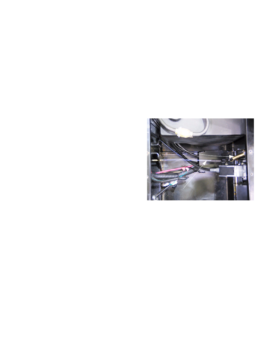
4.33. Operate the differential lock control lever, and
observe the movement of the cable and differen-
tial lock lever on the transaxle.
NOTE: It may be necessary to rotate one of the
rear wheels to align the differential lock dogs
before full engagement will occur. This is nor-
mal.
Figure 4.32
Return spring, disconnected from
console support bracket
Control cable