Diagnosis: confirming transaxle fault, Transmission inkages, Poly bed 4 x 2 drive system – Cub Cadet 4 x 2 Big Country - Poly Bed & Steel Bed User Manual
Page 7
Poly Bed 4 X 2 Drive System
3
3.
DIAGNOSIS: CONFIRMING TRANSAXLE
FAULT
3.1.
Get as much information as possible from the
customer regarding symptoms and circum-
stances.
3.1.
Inspect the vehicle for physical damage and
clues regarding the nature and cause of failure.
3.2.
Carefully operate the vehicle if possible, to con-
firm noises and symptoms.
3.3.
Confirm whether the problem is internal, in the
shift linkage, brake system, or the belt drive sys-
tem (CVT):
•
If a drive gear (forward or reverse) or the differ-
ential lock fail to engage or disengage by manu-
ally overriding the shift mechanism.
•
Shift mechanism issues can be isolated from
internal issues by disconnecting the cables at
the transaxle end, and operating the transaxle
directly.
•
Performance problems such as failure to reach
full speed are likely to be caused by engine,
brake, or belt/clutch issues.
•
Complaints of “lurchy” operation are an indica-
tion that the brakes may be dragging or adjusted
too tight.
•
It is easy to check for dragging brakes by push-
ing the vehicle with the parking brake released,
or by jacking-up the back of the vehicle and
checking the wheels for ease-of rotation.
•
Refer to the “Brake” section of this manual for
service and adjustment information.
•
Gear clash can result from drive being applied to
the input shaft during shifting. Refer to the
“CVT” section of this manual for performance
information.
•
Gear “spit-out” or gear clash when the gear
selector is in Neutral can result from a mis-
adjusted shift linkage. Refer to the “Transmis-
sion Linkage” section of this manual.
•
Under-steer (vehicle is less responsive to steer-
ing wheel in-puts) accompanied by rear wheel
squeal during turning maneuvers indicates that
the differential lock is engaged. If this condition
exists when the differential lock lever is
released, refer to the “Transmission Linkages”
section of this manual.
4.
TRANSMISSION LINKAGES
Shift Control Cable
4.1.
It is possible to remove the gear shift control
cable and gear shift control independently or
together.
4.2.
To gain access to the gear shift control, tilt both
seats forward, and remove the console/cup
holder using a 7/16” wrench. See Figure 4.2.
4.3.
Unbolt the console support plate from the frame
using a 7/16” wrench.
NOTE: The vacuum driven fuel pump is
mounted to the bottom of the console support
plate. It may be unbolted from the plate using a
pair of 7/16” wrenches so that the plate may be
completely removed. It is not absolutely neces-
sary to unbolt the fuel pump if the support plate
is only moved aside for access.
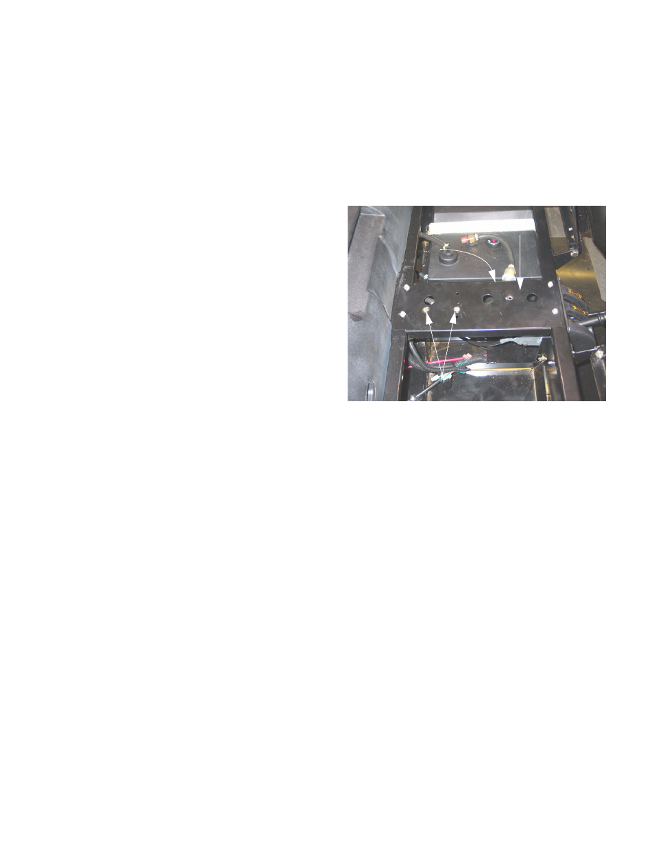
4.4.
Un-hook the differential lock return spring from
the console support plate, and move (or remove)
the plate.
Figure 4.2
Console support plate
Fuel pump mounting bolts
Differential
lock return spring