Poly bed 4 x 2 drive system – Cub Cadet 4 x 2 Big Country - Poly Bed & Steel Bed User Manual
Page 23
Poly Bed 4 X 2 Drive System
19
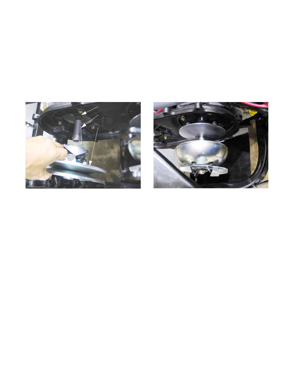
5.50. After the belt is removed, the driven pulley can
be removed: See Figure 5.50.
•
Take the bolt and washer that secure the pulley
onto the transaxle input shaft completely off
using a 12 mm wrench.
•
Slide the pulley off of the input shaft. It may be
necessary to carefully pry on the pulley hub.
•
There is a key between the pulley and the input
shaft, and a spacer between the pulley and the
shoulder on the input shaft.
5.51. If the driven pulley does not function properly,
replace it as a complete unit.
5.52. On installation:
•
Apply a small amount of anti-seize compound to
the input shaft.
•
Confirm that the spacer and key are properly
positioned. The chamfered side of the spacer
should face the shoulder on the crankshaft.
•
Slip the driven pulley all the way onto the input
shaft, and seat it against the spacer.
•
Apply a small amount of thread locking com-
pound such as Loctite 242 (blue) to the threads
of the bolt.
•
Secure the pulley to the input shaft with the bolt
and washer. Tighten the bolt to a torque of: 24 ft-
lb (32 N-m).
5.53. Key points to inspect on the driven pulley are the
ramp surfaces on the cams, and the polymer
buttons that ride against the ramps.
Figure 5.50
Spacer
Key
Driven pulley
5.54. After the belt is removed, the driving pulley can
be removed: See Figure 5.54.
•
Remove the bolt and washer securing the driv-
ing pulley to the engine crankshaft using a 14
mm wrench.
•
Slide the driving pulley off of the crankshaft.
•
There is a key between the pulley and the input
shaft, and a spacer between the pulley and the
shoulder on the crankshaft. The spacer is
notched to fit over the key.
5.55. If the driven pulley does not function properly,
replace it as a complete unit.
5.56. On installation:
•
Apply a small amount of anti-seize compound to
the crankshaft.
•
Confirm that the spacer and key are properly
positioned. The chamfered side of the spacer
should face the shoulder on the crankshaft. The
key should fit through the notch in the spacer.
•
Slip the driven pulley all the way onto the input
shaft, and seat it against the spacer.
•
Apply a small amount of thread locking com-
pound such as Loctite 242 (blue) to the threads
of the bolt.
•
Secure the pulley to the input shaft with the bolt
and washer. Tighten the bolt to a torque of: 31 ft-
lb (42 N-m).
Figure 5.54