Cub Cadet Fun Runner User Manual
Page 10
2-4
Of course, the controller must be able to provide
fully variable speed in each drive mode. The
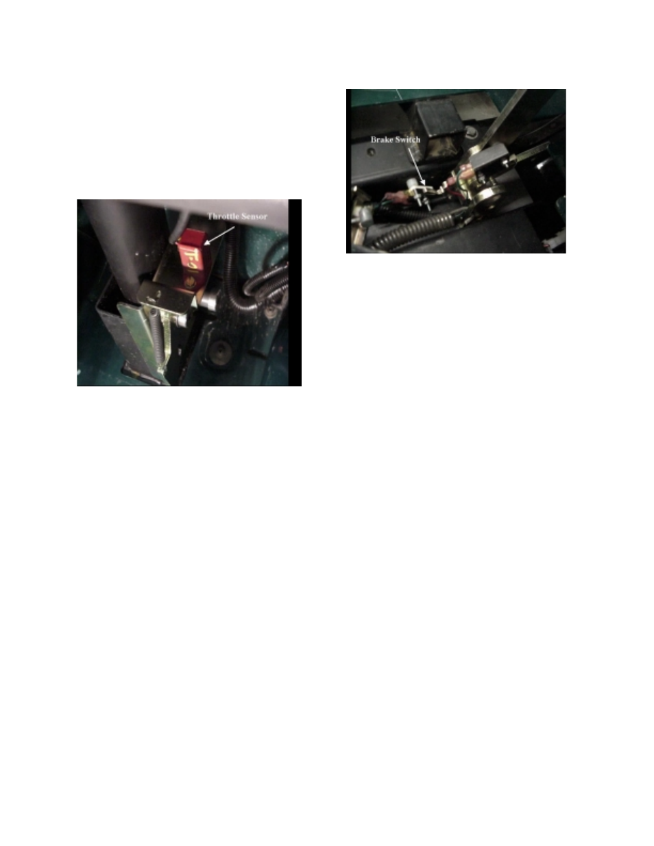
throttle sensor is attached to the accelerator
pedal assembly and wired as an input to the
controller. See Figure 2-9. The sensor is a
potentiometer (a type of variable resistor often
called a pot) that will give a continually variable
signal from the fully released to fully depressed
pedal positions.
Figure 2-9:
The controller will monitor the throttle sensor
signal and adjust the output voltage to the motor
according to the demands of the operator
through the accelerator pedal.
The controller is also equipped with regenerative
braking. Regenerative braking is a feature
where the motor becomes a generator when the
vehicle is coasting or stopping. The kinetic
energy of the vehicle is turning the armature of
the motor through the permanent magnet field
producing a current in the armature that goes to
the controller. The current produced is opposite
of that used by the motor to drive the vehicle.
The controller will pass this current to the battery
pack replenishing a small portion of its charge.
The regenerative braking provides two benefits:
it increases range by adding some charge to the
battery pack and provides braking action that
assists the mechanical brakes. You can feel the
regenerative braking when releasing the
accelerator even if the brake pedal is not
depressed.
The brake switch is connected to the controller
so that when the controller sees an input
indicating the brake has been depressed, it will
not allow power to flow to the motor even if the
accelerator pedal is depressed. See Figure
2-10.
Figure 2-10:
A signal is sent from the charger to the controller
during charging of the FunRunner. When the
controller senses the charging signal, none of
the propulsion modes can be activated. The
output from the charger passes thru the
controller to the batteries.
The FunRunner’s motor controller is unique in
that it controls all of the electrical systems on the
vehicle in addition to the motor. The controller
supplies power to each electrical system when
an input to the controller for the particular
system is activated. You can think of the
controller as a relay for each system. It
operates in a manner similar to a starter relay
connecting power to the starter when the ignition
or start switch energizes the coil of the relay.
An example of this would be the headlights.
The controller sends a voltage to the headlight
switch and monitors this voltage to see if it is
returned (pulled low) by the switch. When the
headlight switch is turned on, it closes
connecting the voltage to the return and the
controller sees the headlight switch wire pulled
low. The controller responds by supplying 12
volts to the headlight and taillight bulbs. The
headlight switch does not feed power directly to
the lights.
Other systems such as turn signals, brake lights,
hazard lights, horn, parking brake indicator and
etc., are controlled in the same way. These are
systems activated by the person operating the
vehicle. The controller will give outputs to other
electrical systems based on inputs not activated
by the operator. Examples are the state of
charge gauge and the speedometer. The
controller will adjust the state of charge meter
based on battery pack voltage. The controller