3 front panel configuration, 4 multi-range and multi-interval scales, 5 total scale configuration – Rice Lake 820i Programmable Indicator/Controller - Installation Manual User Manual
Page 20: Front panel configuration, Multi-range and multi-interval scales, Total scale configuration, Section
16
820i
Installation Manual
Serial commands duplicate the functions available
using the indicator front panel and provide some
functions not otherwise available. Serial commands
can be used to simulate pressing front panel keys, to
configure the indicator, or to dump lists of parameter
settings. See Section 9.0 on page 79 for more
information about using the serial command set.
3.1.3
Front Panel Configuration
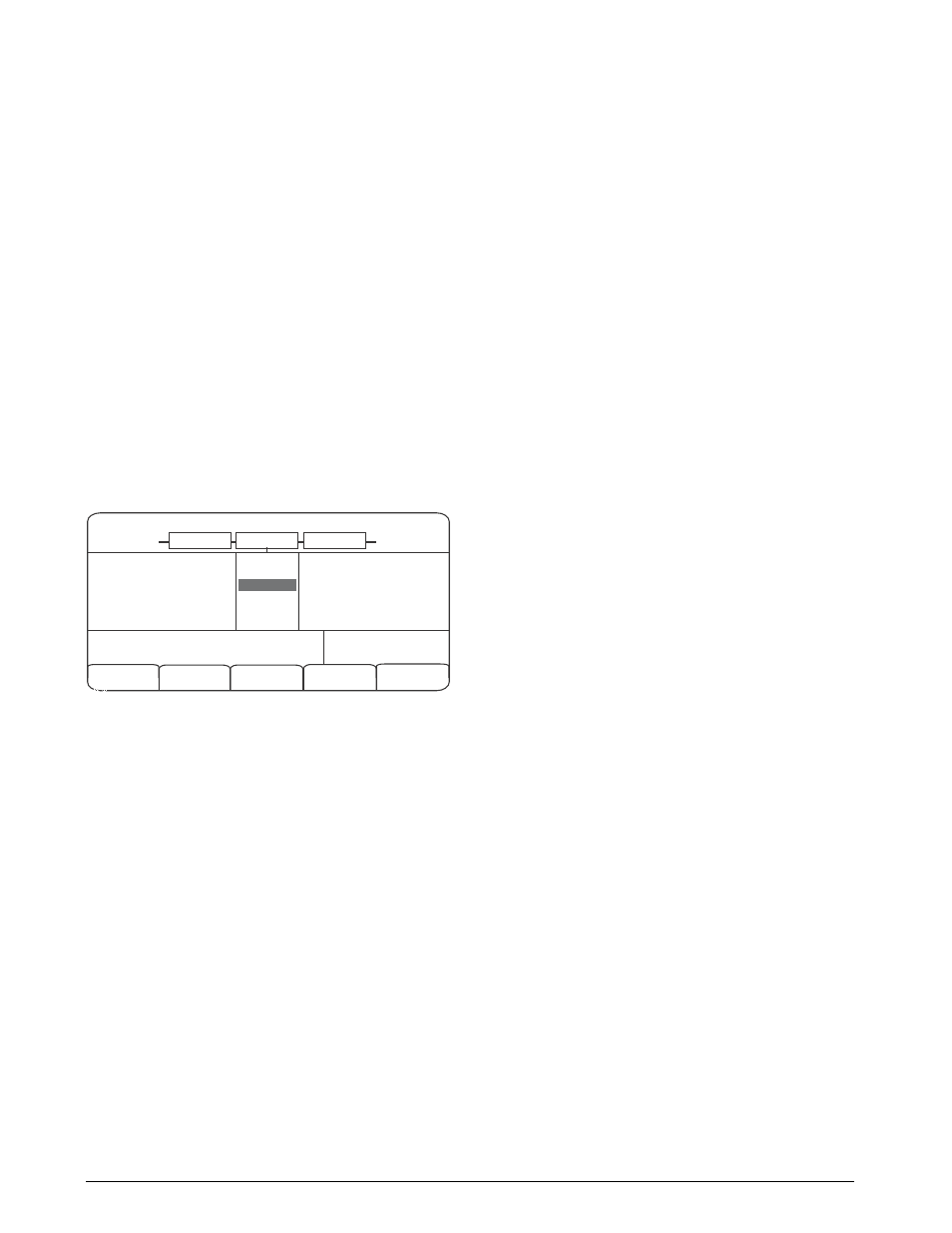
Use the CONFIG submenu under the SCALES menu
to configure A/D scales. For example, in an indicator
with a single-channel A/D card installed in Slot 1, the
Scale Configuration display will show the A/D listed
(
Slot 1 Channel 1
) under the
AVAILABLE A/D’s
column.
Use the
left
navigation key to select the A/D, then
press the center softkey,
Add
. The A/D is then moved
to the Associated A/D’s column. If no other A/D’s are
listed in the
AVAILABLE A/D’s
column, the center
softkey changes to
Done
, as shown in Figure 3-2.
Press
Done
to exit the Scale Configuration display.
See Section 10.3 on page 93 for information about
configuring serial scales.
05/24/2006
02:22PM
Change
Type
Done
CONFIG
SCALE 1
SCALE 2
Scale 1
Scale 2
Scale 3
SCALES ASSOCIATED
A/D’s
AVAILABLE A/D’s
Slot 1 Channel 1
Figure 3-2. Scale Configuration Display
3.1.4
Multi-Range and Multi-Interval Scales
The
820i
supports multi-range and multi-interval
scales of either two or three ranges or intervals.
Multi-range scales provide two or three ranges, each
extending from zero to the maximum capacity
specified for the range, that can specify different scale
intervals (graduations). The scale interval changes as
the applied weight increases but does not reset to
lower range intervals until the scale returns to zero.
Multi-interval scales divide the scale into two or three
partial weighing ranges, each with different scale
intervals. The scale interval changes with both
increasing and decreasing loads applied.
To configure a multi-range or multi-interval scale, use
the SPLIT parameter to select 2RNG or 3RNG (for
multi-range scales), or 2INTVL or 3INTVL (for
multi-interval scales). Selecting a SPLIT value other
than OFF allows specification of decimal point,
display divisions, and maximum capacity for each
range or interval.
The SPLIT parameter is used to enable multi-range or
multi-interval. The SPLIT parameter is in the
SCALES menu, see Figure 3-4, and Table 3-2. After
setting the SPLIT parameter, the
Format
menu
selection will change as shown in Figure 3-6, and
3-4.
If using streaming with multi-range or multi-interval,
the stream must be set to Custom in
Revolution
. The
Tokens for Secondary and Tertiary Units must be set
to L or K to match the Primary, refer to the Serial
Menu, Tokens Parameter, in Section
30.
They can be set using
Revolution
or through the front
panel.
In multi-range, each range has its own capacity and
display division, extending from zero. The scale
display division will increase at the entered range
capacities, either two or three ranges. Once the range
has increased to the next level, the display division
will remain in new range until the scale returns to
zero. The tare value can be taken in any range.
For example,
Range 1 is 0 - 3000 x 1 lb.
Range 2 is 0 - 10,000 x 5 lb.
In multi-interval, the scale has one capacity, which is
segmented into weighing intervals, either two or three
intervals, each with different display division sizes.
As the weight value exceeds an interval or set interval,
the display division will increase, as the weight falls
below an interval or set interval, the display division
will decrease. The tare can only be taken in the first
interval.
For example,
Range 1 is 0-30 x 0.01 lb.
Range 2 is 30 - 60 x 0.02 lbs.
3.1.5
Total Scale Configuration
The output of A/D scales, serial scales, or
iQUBE
systems can be configured to function as a total scale.
Once configured and calibrated, the total scale can be
used as a source for other system functions, including
streaming, setpoints, print formatting, and analog
output.
To set up a total scale from the indicator front panel,
use the scale configuration display (see Figure 3-2) to
select the A/D scales or
iQUBE
systems to configure
as a total scale. (Use the
Change Type
softkey to show
available A/D scales or
iQUBE
systems; use the right
navigation key to select the total scale sources.) In
Revolution
, assign the total scale to an unused
position then select source scales from the existing
A/D scales or
iQUBE
systems.