5 slot assignments, 6 enclosure reassembly, 7 cpu board removal – Rice Lake 820i Programmable Indicator/Controller - Installation Manual User Manual
Page 14: Slot assignments, Enclosure reassembly, Cpu board removal, Section
10
820i
Installation Manual
2.5
Slot Assignments
Table 2-4 lists the slot numbers, CPU board connectors, and configuration assignments made for both onboard
and expansion card functions in the
820i
2-3 for connector locations.
Table 2-4. 820i Slot Assignments
Slot Number
Connector
Function
Configured As
0
Connector J5
Onboard digital I/O
Slot 0, bits 1–8
Connectors J9, J1, J10, J11
Onboard serial communications
Ports 1–4
1
Connectors J7, J8
Onboard single- or dual-channel A/D
Channel 1, Channel 2
2
Connector J6 (option card slot)
Dual-channel serial expansion card
Ports 7–8
Digital I/O expansion card
Slot 2, bits 1–24
Analog input card
Slot 2, channels 1–2
Analog output card
Analog 2
Pulse input card
Pulse 2
Memory expansion card
Memory 2
Bus communications cards
Bus Option 2
2.6
Enclosure Reassembly
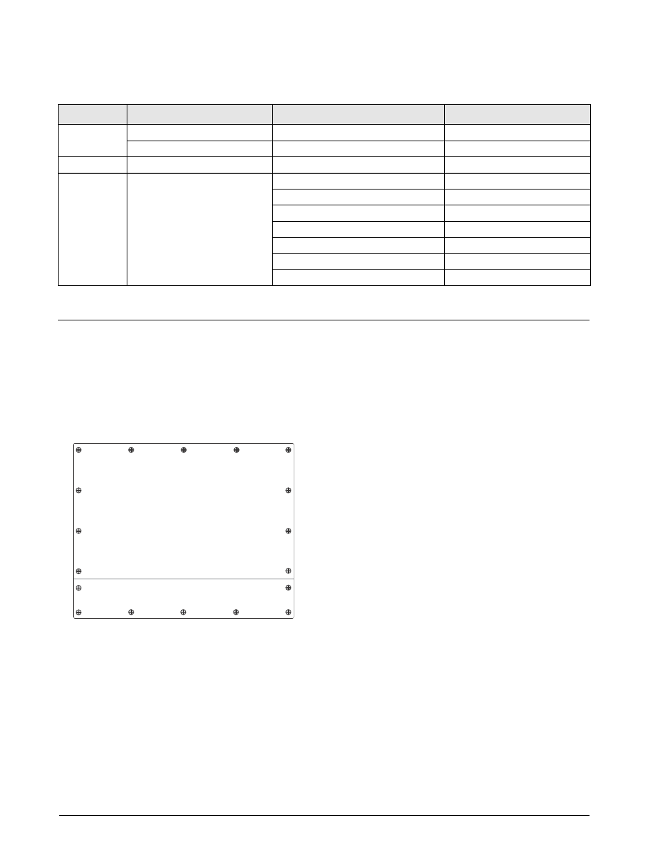
Once cabling is complete, position the backplate over
the enclosure and reinstall the backplate screws. Use
the torque pattern shown in Figure 2-4 to prevent
distorting the backplate gasket. Torque screws to 15
in-lb (1.7 N-m).
1
3
5
14
17
16 12
9
8
7
10
11
18
15
4
2
6
13
T o r q u e b a c k p l a t e s c r e w s
t o 1 5 i n - l b ( 1 . 7 N - m )
Figure 2-4. 820i Enclosure Backplate
Torqued screws may become less tight as the gasket is
compressed during torque pattern, therefore a second
torque is required using the same pattern and torque
value.
2.7
CPU Board Removal
If you must remove the
820i
CPU board, use the
following procedure:
1. Disconnect power to the indicator. Remove
backplate as described in Section 2.2 on
2. Unplug connectors for power to the board,
serial communications, digital I/O, and any
installed option cards.
3. Remove any installed option cards.
4. Remove the five phillips head screws and two
kep nuts from the CPU board.
5. Gently lift up the CPU board, then disconnect
bottom-side connectors for power to display,
ribbon cable, and keypad connector.
6. Remove CPU board from the enclosure. If
necessary, cut cable ties to shift cables out of
the way.
To replace the CPU board, reverse the above
procedure. Be sure to reinstall cable ties to secure all
cables inside the indicator enclosure.