0 installation, 1 unpacking and assembly, 2 enclosure disassembly – Rice Lake 820i Programmable Indicator/Controller - Installation Manual User Manual
Page 10: 3 cable connections, 1 cable grounding, Installation, Unpacking and assembly, Enclosure disassembly, Cable connections, Cable grounding
6
820i
Installation Manual
2.0
Installation
This section describes procedures for connecting load
cell, digital I/O, and serial communications cables to
t h e
8 2 0 i
i n d i c a t o r.
A s s e m b l y d r a w i n g s a n d
replacement parts lists for the universal model are
included for the service technician. See Section 10.11
on page 101 for dimension drawings.
• Use a wrist strap to ground yourself and protect
components from electrostatic discharge (ESD)
when working inside the indicator enclosure.
• This unit uses double pole/neutral fusing which
could create an electric shock hazard. Procedures
requiring work inside the indicator must be
performed by qualified service personnel only.
• The supply cord serves as the power disconnect
for the
820i
. The power outlet supplying the
indicator must be installed near the unit and be
easily accessible.
2.1 Unpacking and Assembly
Immediately after unpacking, visually inspect the
820i
t o e n s u r e a l l c o m p o n e n t s a r e i n c l u d e d a n d
undamaged. The shipping carton should contain the
indicator, this manual, and a parts kit. If any parts
were damag ed in sh ipm en t, notify Rice Lake
Weighing Systems and the shipper immediately.
See Section 2.9 on page 11 for parts kit contents.
2.2
Enclosure Disassembly
The indicator enclosure must be opened to install
option cards and to connect cables for installed option
cards.
The
820i
has no on/off switch. Before
opening the unit, ensure the power cord is
disconnected from the power outlet.
Ensure power to the indicator is disconnected, then
place the indicator face-down on an antistatic work
mat. Remove the screws that hold the backplate to the
enclosure body, then lift the backplate away from the
enclosure and set it aside.
2.3
Cable Connections
The universal model of the
820i
provides six cord
grips for cabling into the indicator: one for the power
cord, five to accommodate other cabling. Install plugs
in all unused cord grips to prevent moisture from
entering the enclosure.
2.3.1
Cable Grounding
Except for the power cord, all cables routed through
the cord grips should be grounded against the
indicator enclosure. Do the following to ground
shielded cables:
• Use the lockwashers, clamps, and kep nuts
provided in the parts kit to install grounding
clamps on the enclosure studs adjacent to cord
grips. Install grounding clamps only for cord grips
that will be used; do not tighten nuts.
• Route cables through cord grips and grounding
clamps to determine cable lengths required to
reach cable connectors. Mark cables to remove
insulation and shield as described below:
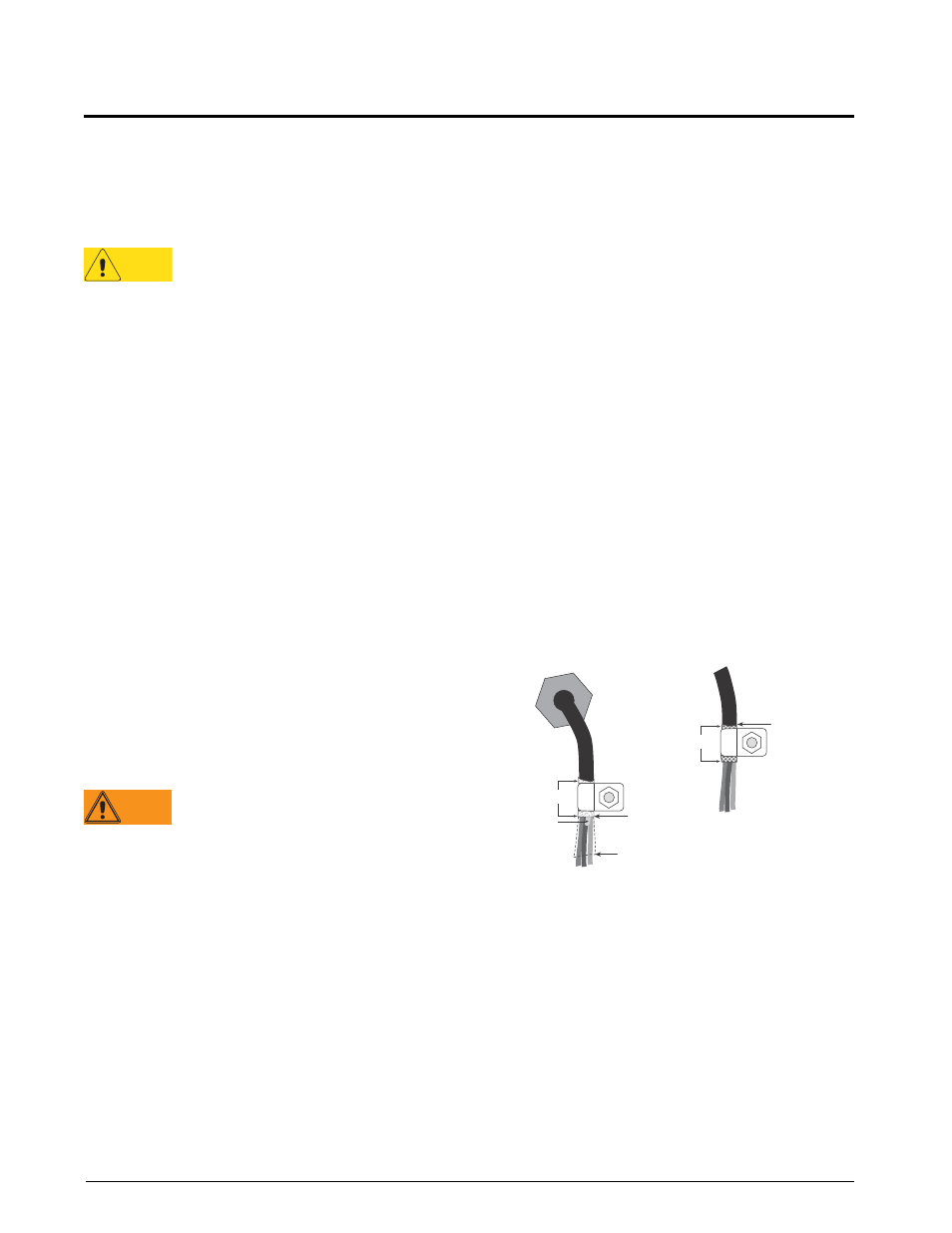
• For cables with foil shielding, strip insulation
and foil from the cable half an inch (13 mm)
past the grounding clamp (see Figure 2-1). Fold
the foil shield back on the cable where the cable
pa sses through the cl amp. Ensure silver
(conductive) side of foil is turned outward for
contact with the grounding clamp.
• For cables with braided shielding, strip cable
insulation and braided shield from a point just
past the grounding clamp. Strip another half
inch (15 mm) of insulation only to expose the
braid where the cable passes through the clamp
(see Figure 2-1).
Figure 2-1. Grounding Clamp Attachment for Foil-Shielded
and Braided Cabling
• For load cell cables, cut the shield wire just past
the grounding clamp. Shield wire function is
provided by contact between the cable shield and
the grounding clamp.
• Route stripped cables through cord grips and
clamps. Ensure shields contact grounding clamps
as shown in Figure 2-1. Tighten grounding clamp
nuts.
• Finish installation using cable ties to secure cables
inside of indicator enclosure.
Caution
Warning
Cor d grip
Insulated cable
Foil (silver side out)
Gr ounding clamp
Shield wir e (cut)
Length of foil before folding
back on cable insulation
Cut insulation here
for foil-shielded cables
Braid
Cut insulation here
for braided cables
NOTE: Install lockwashers
first, against enclosure,
under grounding clamp