4 digital i/o, 4 installing option cards, Digital i/o – Rice Lake 820i Programmable Indicator/Controller - Installation Manual User Manual
Page 12: Installing option cards
8
820i
Installation Manual
Port 3 uses connector J1 to support USB, Ethernet,
and fiber-optic interface cards.
Note
Installation of option cards in connector J1
requires removal of the J1/J10 port
selection jumper (see Figure 2-3 on
page 9). Removing the jumper disables RS-232
communications through connector J10. For the USB
interface card only, connections for simultaneous
R S - 2 3 2 ( c o n f i g u r e d a s P o r t 3 ) a n d U S B
communications (Port 2) are provided on the USB
interface card.
See the communications interface card installation
instructions for more information.
2.3.4
Digital I/O
Digital inputs can be set to provide many indicator
functions, including all keypad functions. Digital
inputs are active low (0 VDC), inactive high (5 VDC).
Digital outputs are typically used to control relays that
drive other equipment. Outputs are designed to sink,
rather than source, switching current. Each output is a
normally open collector circuit, capable of sinking 24
mA when active. Digital outputs are wired to switch
relays when the digital output is active (low, 0 VDC)
with reference to a 5 VDC supply.
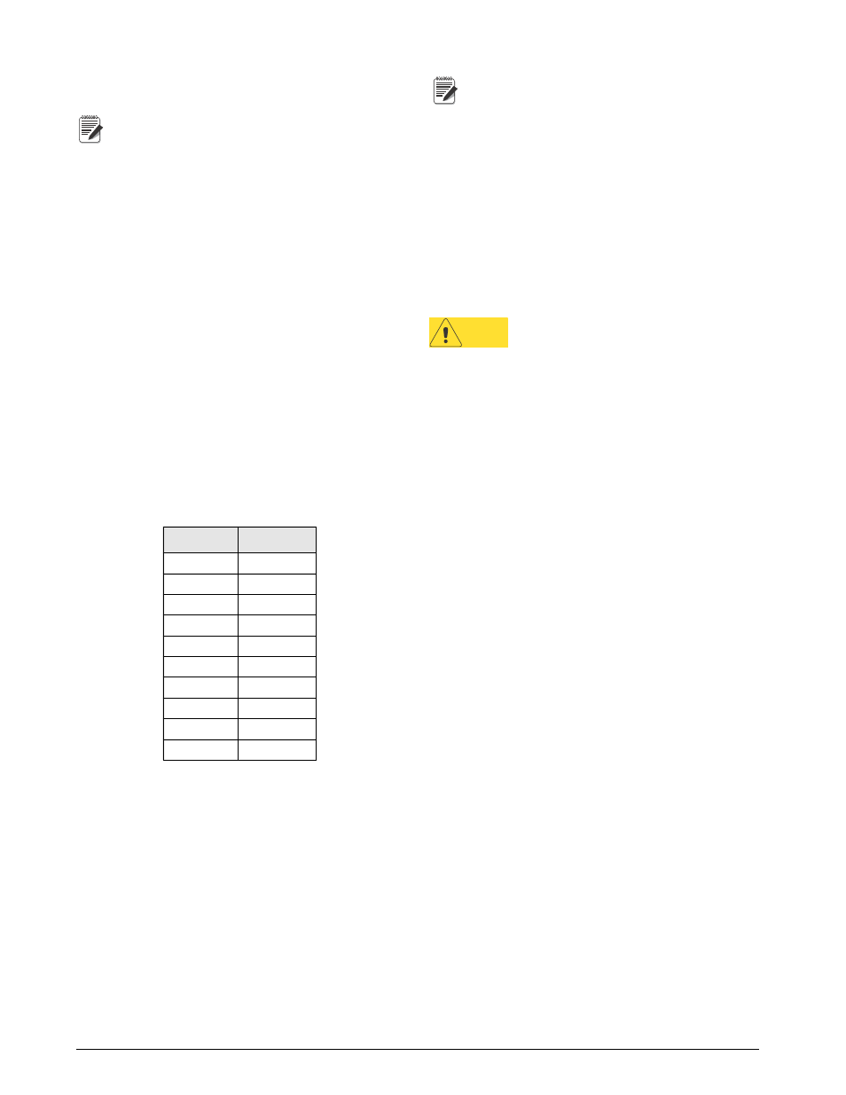
Table
2-3 shows the pin assignments for connector J5.
Table 2-3. J5 Pin Assignments (Digital I/O)
J5 Pin
J5 Signal
1
+5 VDC
2
GND
3
DIO 1
4
DIO 2
5
DIO 3
6
DIO 4
7
DIO 5
8
DIO 6
9
DIO 7
10
DIO 8
Digital inputs and outputs are configured using the
DIG I/O menu. See Section 3.2.7 on page 44 for
configuration information.
An optional 24-channel digital I/O expansion card,
PN 67601, is available for applications requiring more
digital I/O channels.
Note
Digital I/O points can be configured to
count active pulse inputs by setting them to
PROGIN (DIGIN menu) and using the
iRite-IDE
DigInSsBbActivate handler with a timer to
turn the handler on and off. However, the fastest pulse
rate that can be counted using a digital input is 10Hz
(10 pulses per second). More demanding applications
can use the pulse input option card (PN 67603) to
count pulses in the 4–4000Hz range.
2.4
Installing Option Cards
Each option card is shipped with installation
instructions specific to that card. The general
procedure for all option cards is as follows:
Caution
Option cards are not hot-pluggable.
Disconnect power to the
820i
before
installing option cards.
1. Disconnect power to the indicator. Remove
backplate as described in Section
2. Carefully align the large option card connector
with connector J6 on the CPU board (see
Figure 2-3 on page 9) or J1. Press down to seat
the option card in the CPU board connector.
3. Use the screws provided in the option kit to
secure the other end of the option card to the
threaded standoffs on the CPU board (see
2-3).
4. Make connections to the option card as required.
Use cable ties to secure loose cables inside the
enclosure. When installation is complete,
reassemble the enclosure as described in
The
820i
automatically recognizes all installed option
c a r d s w h e n t h e u n i t i s p o w e r e d o n . N o
hardware-specific configuration is required to identify
the newly-installed card to the system.