2 load cells, 3 serial communications, Load cells – Rice Lake 820i Programmable Indicator/Controller - Installation Manual User Manual
Page 11: Serial communications
Installation
7
2.3.2
Load Cells
To attach cable from a load cell or junction box to the
820i
, route the cable through the cord grip and ground
the shield wire as described in Section 2.3.1 on
6.
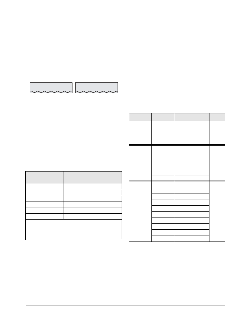
Next, remove load cell connector J7 or J8 from CPU
board. Wire the load cell cable from the load cell or
junction box to the connector as shown in Table
J7
LOAD CELL
CONNECTOR
J8
LOAD CELL
CONNECTOR
+SIG
–SIG
+SENS
–SENS
+EXC
–EXC
+SIG
–SIG
+SENS
–SENS
+EXC
–EXC
Figure 2-2. Load Cell Connectors
If using 6-wire load cell cable (with sense wires),
remove jumpers JP1 and JP2 before reinstalling
connector J7. For 4-wire installation, leave jumpers
JP1 and JP2 on. For 6-wire load cell connections on
dual-channel A/D cards, remove jumpers JP3 and JP4
for connections to J8.
When connections are complete, reinstall load cell
connector on the CPU board header and use two cable
ties to secure the load cell cable to the inside of the
enclosure.
Table 2-1. Load Cell Connector Pin Assignments
J7 or J8
Connector Pin
Function
1
+SIG
2
–SIG
3
+SENSE
4
–SENSE
5
+EXC
6
–EXC
•
For 6-wire load cell connections to connector J7, remove
jumpers JP1 and JP2.
•
For 6-wire load cell connections to connector J8 (dual A/D
boards), remove jumpers JP3 and JP4.
2.3.3
Serial Communications
Communications ports on the
820i
CPU board support
PS/2-type remote keyboard, full duplex RS-232, 20
mA output, or RS-485 communications at up to
115200 bps. Optional communications cards support
USB, Ethernet, and fiber-optic connections to the
820i
.
To attach serial communications cables, route the
cable through the cord grip and ground the shield wire
as described in Section 2.3.1 on page 6. Remove the
serial connector from the CPU board and wire to the
connector. Once cables are attached, plug the
connector into the header on the board. Use cable ties
to secure serial cables to the inside of the enclosure.
Table 2-2 shows the pin assignments for Ports 1, 2,
and 4. Port 1 supports remote keyboard attachment of
PS/2-type personal computer keyboards (see
Section 10.9 on page 99 for information about the
PS/2 keyboard interface.)
Table 2-2. Serial Port Pin Assignments
Connector
Pin
Signal
Port
J9
1
CLK
1
2
+5V
3
GND
4
DATA
J10
1
GND
2
2
RS-232 RxD
3
RS-232 TxD
4
RS-232 RTS
5
RS-232 CTS
6
GND
J11
1
GND
4
2
N/C
3
N/C
4
RS-485 A
5
RS-485 B
6
+20mA OUT
7
–20mA OUT
8
GND
9
RS-232 RxD
10
RS-232 TxD
Serial ports are configured using the SERIAL menu.
See Section 3.2.2 on page 30 for configuration
information.
An optional dual-channel serial communications
expansion card, PN 67604, is also available. The
serial expansion card provides two additional serial
ports, assigned as port numbers 7 and 8. One port on
the serial expansion card supports four-wire RS-485
communications. Both ports on the expansion card
can support RS-232 or 20mA connections.