Ounting, Evice, Onnections – ETS-Lindgren 2090 Controller User Manual
Page 33: Rack mounting, Device connections
Model 2090 Multi-Device Controller
RACK MOUNTING
The Model 2090 controller can be ordered with a rack
mount option (Part # 540037). This option can be either
factory or field installed. The rack mount option provides
capability for installing the controller in a universal E. I. A.
48.26 cm (19.0 in) rack. A rack height of 13.34 cm (5.25
in) is required.
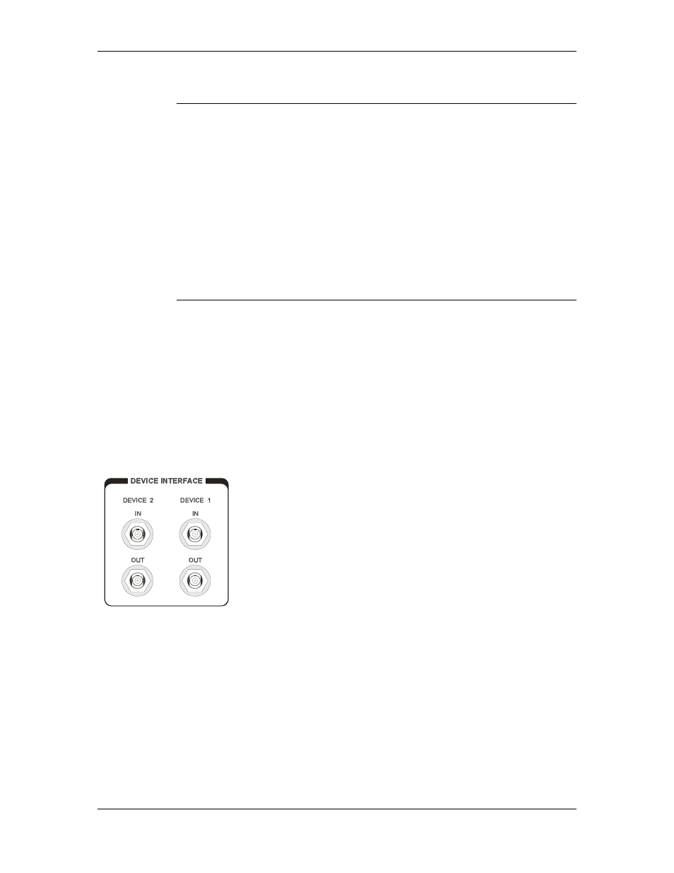
DEVICE CONNECTIONS
Any combination of primary devices (towers, turntables,
reverberation paddles, MAPS, etc.) can be connected to the
two Device Interface ports located on the rear panel of the
controller. For easy set up of an EMC facility, it is
recommended that the tower be connected to the Device 1
interface port and the turntable be connected to the Device
2 interface port, since these are the controller's default
settings. Reverberation paddles and each axis of the Multi-
Axis Positioner behave similar to turntables, and should be
configured as such. Primary device connection is
accomplished by way of a dual fiber cable included with
the device. This cable terminates into two ST connectors
that are identical at both ends. The cable is symmetrical;
either end can be connected to the controller. A fiber optic
cable that is connected to the IN port of a device should, at
the other end, be connected to the primary OUT port of the
motor base. A fiber connected to the OUT port of the
device should, at the other end, be connected to the primary
IN port of the motor base. Older motor base designs have
only one fiber optic connector pair, while the newest motor
©ETS-Lindgren, April 2006
33
Revision G– P#399199