Tandard, Anel, Escription – ETS-Lindgren 2090 Controller User Manual
Page 29: Figure 3 model 2090 standard back panel, Standard back panel description
Model 2090 Multi-Device Controller
Model 2090 Multi-Device Controller
©ETS-Lindgren, April 2006
29
Revision G– P#399199
STANDARD BACK PANEL DESCRIPTION
IEEE
488
GPIB
-
FUSE
2 A: 250 V T
115/230 V
50/ 60 Hz
100 VA MAX.
LINE INPUT
ATTENTION
Pour emploi par le
personnel de laboratoire.
CAUTION
For laboratory use by
qualified personnel.
DEVICE INTERFACE
DEVICE 2
IN
IN
DEVICE 1
OUT
OUT
AUXILIARY CONTROL
AUX 1
AUX 2
AUX 3
AUX 4
2
3
4
5
6
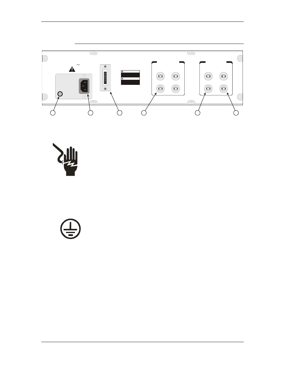
3 Model 2090 Standard Back Panel
1
Figure
2.
ER INLET – This is the IEC 320 power inlet.
Attach an appropriate power cord between this inlet and the
personal injury or instrument damage and will void the
3.
or other GPIB
bus controlling device using a standard GPIB cable.
4.
1.
AC POWER FUSE – This is the AC power fuse holder.
Replace the fuse with the power off and the power cord
disconnected from the unit, and only with a fuse of the
same rating. Failure to do so may cause personal injury or
instrument damage and will void the warranty.
IEC POW
power mains. This is a grounded outlet and provides the
safety earth ground for the instrument. Never attempt to
defeat the safety features of the device. Doing so may cause
warranty.
GPIB
PORT – This is the IEEE 488 GPIB interface port.
It is used to connect the Model 2090 to a PC
AUXILIARY
CONTROL – These are the ST-type fiber
optic output connectors for the four auxiliary device
©ETS-Lindgren, April 2006
29
Revision G– P#399199