Elecraft K3 Owner's Manual User Manual
Page 78
78
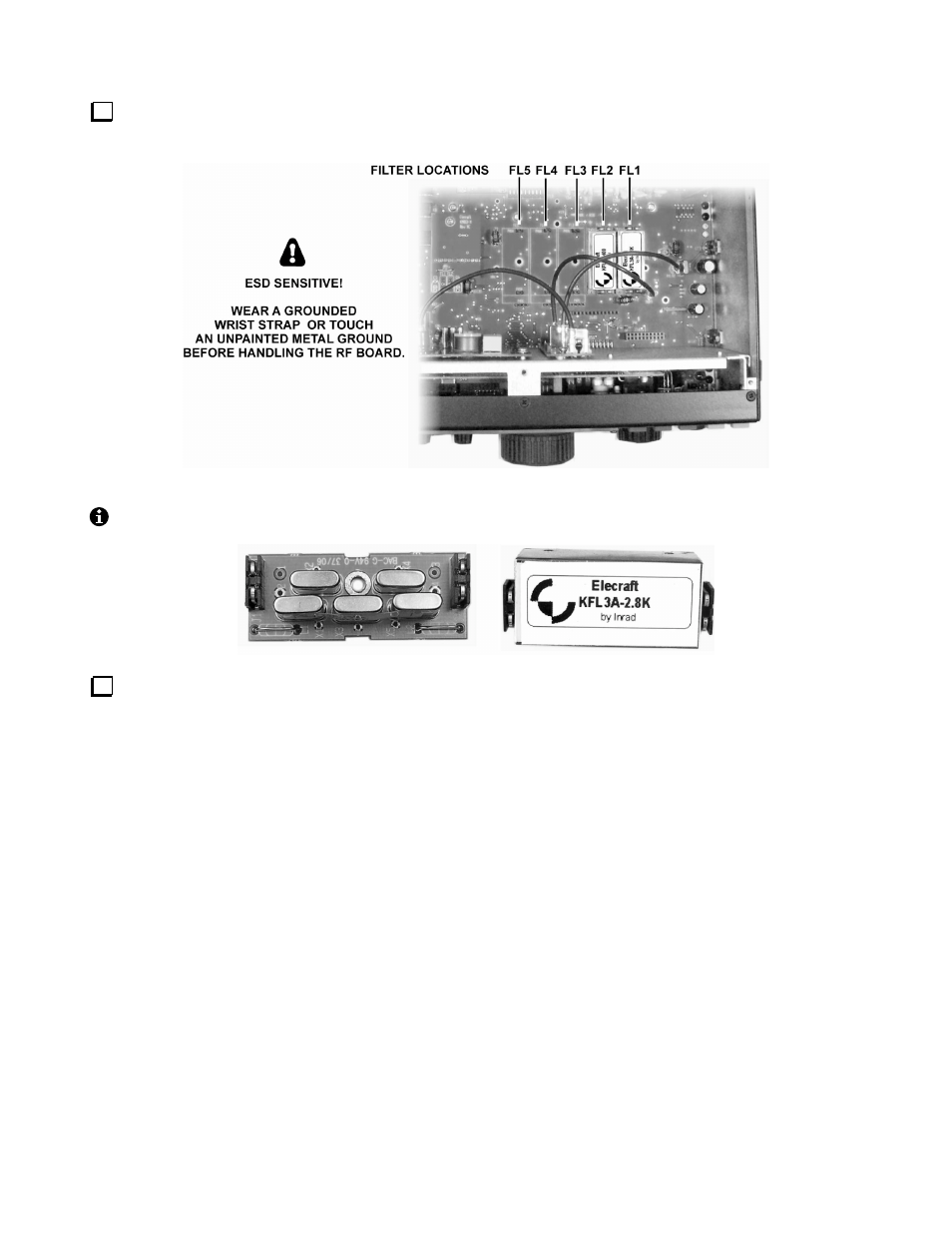
Locate the crystal filters you presently have installed in slots FL1 - FL5 on the RF board (or sub receiver).
There may be a mix of 5-pole filters (below left) and 8-pole filters (right).
Review the information below to ensure that your crystal filter setup conforms to K3 requirements.
You can install up to five crystal filters (FL1-FL5) on the RF board, and five on the sub receiver (KRX3). FM
operation requires a 13 kHz wide filter. AM transmit requires a 6 kHz filter, and SSB/DATA/CW transmit
requires a 2.7 or 2.8 kHz filter; other bandwidths can be used for receive in these modes. Filters as narrow as
200 Hz can be used for CW and narrow-band data receive. A mix of 5-pole and 8-pole filters can be used.
There are two rules regarding where these filters can be installed in the K3 and how they’re used:
Rule #1: If you plan to use a particular filter for both transmitting and receiving (main receiver), you’ll need to
install it on the RF board. You can optionally install a filter of the same or similar bandwidth on the sub
receiver for receive-only use. (This is recommended since it will keep the receivers identical.)
Rule #2: You can install any filter in any slot, and can leave any slot empty in anticipation of installing a crystal
filter there later. However, you should install the widest filter closest to FL1, the next widest to its left, etc. Here
are two examples that could each apply to either receiver, assuming you follow the rules above:
FL1
6 kHz (AM)
FL1 {saved for FM filter}
FL2
2.7 kHz (SSB/CW/DATA)
FL2 6 kHz (AM)
FL3
1.8 kHz (SSB/CW/DATA)
FL3 2.8 kHz (SSB/CW/DATA)
FL4
500 Hz (CW/DATA)
FL4 {saved for variable-bandwidth filter}
FL5
200 Hz (CW/DATA)
FL5
400 Hz (CW/DATA)