Elecraft K3 Owner's Manual User Manual
Page 32
32
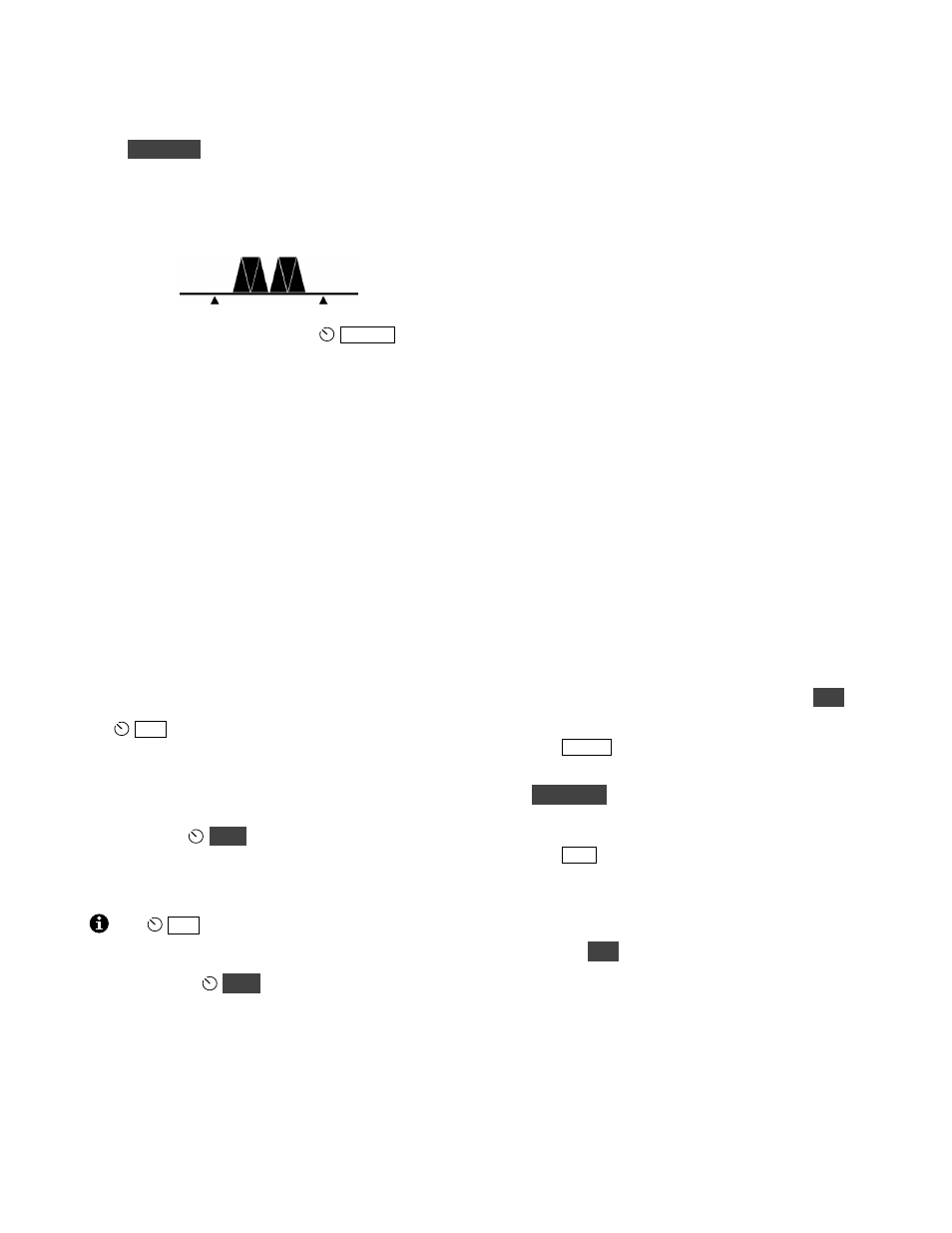
RTTY Dual-Tone Filter (DTF)
Hold
D U A L P B
to turn on the RTTY dual-tone
filter (DTF). This creates two filters, one centered
on the mark tone, the other on space, which can
often improve RTTY copy. The filter graphic
changes to reflect this (see below).
When DTF is on, the range of the
WID T H
control is adjusted to better match the
characteristics of the filter. SHIFT, LOCUT and
HICUT are disabled.
The dual-tone filter can be used with
AFS K A
and
FSK D
. The on/off state of DTF is saved
independently for each of these modes.
FSK Transmit Polarity
You can invert the logic level of the FSK IN line in
FSK D mode using CONFIG:FSK POL. This
should be used only with external keying via
computer programs such as MMTTY; it is not
recommended for use with CW-to-DATA (pg. 34).
Mic Gain, ALC, and Monitor Level
If you’re using an audio-shift transmit mode (
LSB
,
USB
,
DAT A A
, or
AFS K A
), you’ll need to set
the
M IC
level while watching the ALC meter.
You can use the same procedure outlined for voice
modes (pg. 28), except that speech compression
should not be used.
In all cases (SSB modes as well as DATA), you can
optionally use
M O N
to monitor your data
signals. The procedure given for voice modes can
be used (pg. 28). Voice-mode and DATA-mode
monitor levels are independent.
The
M IC
setting does not apply to direct
modulation data modes (
FSK D
and
PSK D
),
since no audio is used for transmission. However,
you can still use
M O N
to monitor the signals.
AMTOR / PacTOR
AMTOR, PacTOR and similar modes can reliably
transfer data – including e-mail – via HF radio
networks. New modes are under development that
may provide even greater reliability. Applications
include maritime mobile and emergency
communications where the K3’s light weight and
excellent receive performance are advantageous.
General information regarding K3 set up for these
modes appears below.
•
Frequency stability is important in these modes.
A 1-PPM TCXO is available (KTCXO3-1).
•
Connect modem audio I/O to the K3’s LINE
OUT and LINE IN jacks (for LINE OUT, use
the TIP contact of a stereo plug). A PTT
connection is also usually required. If the
modem operates from 12 V (0.5 A or less), it
can be powered from the K3’s 12 VDC output.
•
Set up the modem (if applicable). Settings may
vary depending on the data mode being used.
•
Locate CONFIG:LIN OUT and set it to 10. A
different level may be better for your modem.
•
The K3’s SYNC DATA feature can be used to
minimize T-R delays (it forces the same crystal
filter to be used for both receive and transmit).
Locate CONFIG:SYNC DT. Assign it to a
programmable function (e.g., by holding
P F 1
),
then exit the menu.
•
Tap
M O D E
to select
DAT A
.
•
Select an appropriate data sub-mode by holding
D A T A M D
, then rotating VFO B.
DAT A A
(generic data mode, USB) is used in most cases;
see pg. 31 for alternatives, such as
AFS K A
.
Tap
A F X
to exit the parameter display.
•
Locate MAIN:MIC SEL and set the audio
source for data to
LIN E IN
. Exit the menu.
•
If you wish to use SYNC DATA, turn it on by
holding
P F 1
(or the switch used above). The
–S
icon will appear. A CONFIG:PTT RLS
value of 10 to 12 may be ideal in this case.
•
Some modes may have very high duty cycles;
use less than full power output if required.
Refer to your application software for instructions
regarding email set up and other operating details.