Elecraft K3 Owner's Manual User Manual
Page 6
6
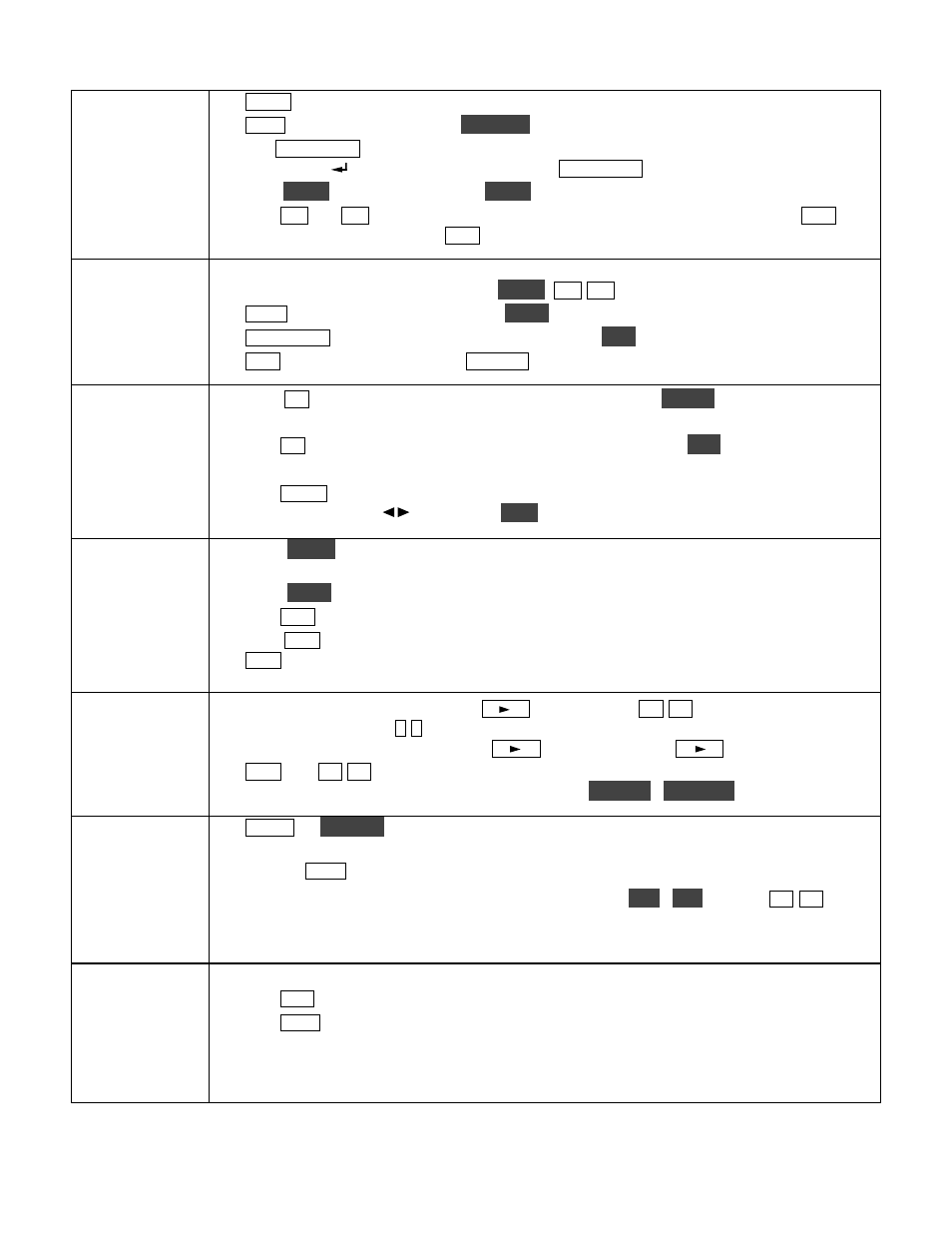
VFOs
and RIT/XIT
•
R A T E
{21} selects 10 or 50 Hz VFO/RIT tuning. See VFO menu entries, pg. 53.
•
F IN E
{21} selects 1-Hz steps.
C O A R S E
selects large steps (MAIN menu, VFO CRS).
• Tap
F R E Q E N T
{21} to enter frequency in MHz using numeric keypad & decimal point.
Tap return ( ) to complete the entry, or tap
F R E Q E N T
again to cancel. (Pg. 15.)
• Hold
S C A N
to start/stop scanning.
S C A N
must be preceded by a memory recall (pg. 40).
• The
R IT
and
X IT
offset knob {17} has LEDs that show -/0/+ offset (pg.16). Tap
C L R
{16} to zero the offset. Hold
C L R
for > 2 sec. to add the offset to VFO A, then zero it.
Transmit,
ATU, and
Antenna
Controls
• The
TX
LED {4} indicates that the K3 is in transmit mode. The
∆f
LED turns on if the
RX and TX frequencies are unequal (
S P L IT
,
R IT
/
X IT
, cross-mode, etc.). (Pg. 13.)
•
X M IT
{8} is equivalent to PTT {35}.
T U N E
puts out full CW power in any mode.
•
A T U T U N E
{8} initiates antenna matching (pg. 22).
A T U
enables or bypasss the ATU.
•
A N T
selects
ANT 1
or
ANT 2
.
R X A N T
selects main or
RX
antenna (KXV3).
NB, NR,
and Notch
• Tap
N B
{12} to enable DSP and I.F. noise blanking. Hold
L E V E L
to set DSP NB level
(VFO A) and I.F. NB level (VFO B). Fully CCW is OFF in both cases. (Pg. 25.)
• Tap
N R
{12} to turn on noise reduction (saved per-mode). Hold
A D J
to tailor noise
reduction for the present band conditions (pg. 25).
• Tap
N T C H
{12} once to select auto-notch (
NTC H
icon), and a second time to select
manual notch (adds
icon). Hold
M A N
to adjust manual notch frequency. (Pg. 25.)
SPLIT,
BSET,
and SUB
• Hold
S P L IT
{13} to enter split mode (RX on VFO A, TX on VFO B). If VFOs A and B
are on different frequencies in SPLIT mode, the Delta-F LED (
∆f
) will turn on (pg. 13).
• Hold
B S E T
{13} to adjust VFO B / sub RX settings independently of VFO A (pg. 37).
• Tap
S U B
{20} to turn on the sub receiver (pg. 37). VFO B controls its frequency.
• Hold
S U B
{20} to link the two VFOs (VFO A is then the master). A 2-second hold of
S U B
engages diversity mode (pg. 38). SPLIT operation is possible in diversity mode.
Memories,
Messages, and
DVR
• To store a frequency memory, tap
V M
{14}, then: tap
M 1
-
M 4
{15} to save a per-band
quick memory; or tap
0
-
9
to save a general-purpose quick memory; or rotate VFO A to
select from memories 0-99, then tap
V M
again to save. Tap
M V
to recall. (Pg. 16.)
•
R E C
and
M 1
-
M 4
{15} are also used to record & play voice/CW/DATA messages. The
KDVR3 option is required for voice messages and
A F R E C
/
A F P L A Y
(pg. 29).
Menus and
Switch Macros
•
M E N U
&
C O N F IG
{8} access the MAIN and CONFIG menus. VFO B selects entries;
VFO A changes parameters. In general, CONFIG menu entries are used less often.
• Tapping
D IS P
{8} within menus shows information about each entry on VFO B (pg 52).
• Menu entries can be assigned to programmable switches
P F 1
,
P F 2
{16} and
M 1
-
M 4
{15}
(pg 52). These switches can also execute often-used macros like “SPLIT, A>B, move VFO
B up 5,” with a single tap or hold. See the K3 Programmer’s Reference for examples.
Other
Features
• RX and TX EQ (MAIN menu) provide 8 bands of receive/transmit equalization (pg. 35).
• Tap
A F X
{18} to enable the selected audio effect (see CONFIG:AFX MD, pg. 52).
• Tap
D IS P
{8} and use VFO B to show time, supply voltage, etc. on VFO B (pg. 36).
• The ALARM function (MAIN:ALARM menu entry) can be used to remind you about a
contest, net, or QSO schedule, and can even turn the K3 on at alarm time (pg. 36).
• The KIO3 module provides a rich set of AF {33} and digital {32} I/O (pg. 17).