Ca 9 1, Ba 8 i – HP 2566C User Manual
Page 61
Attention! The text in this document has been recognized automatically. To view the original document, you can use the "Original mode".
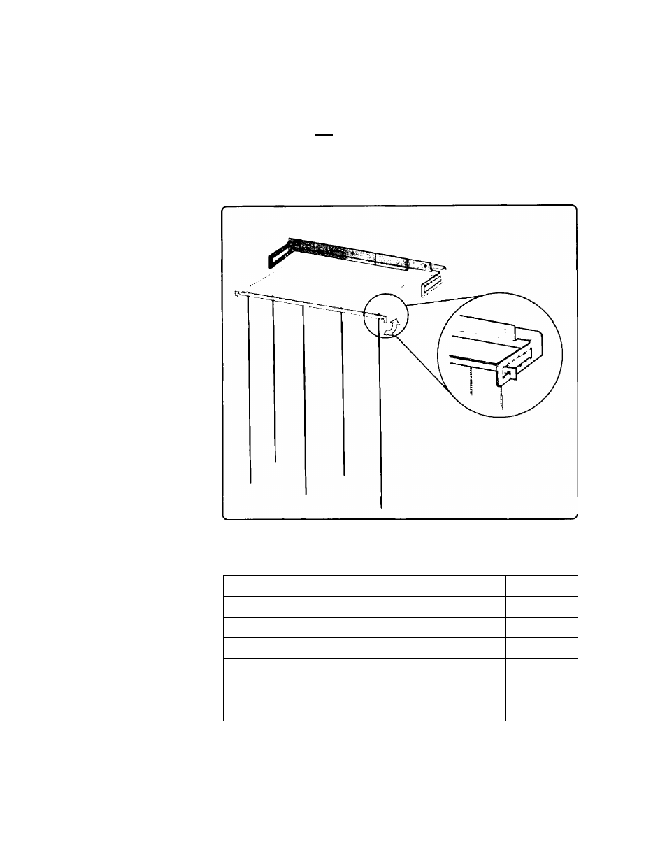
Refer to Table 4-2 for the recommended position of the door chains
for your paper size. (The Operator Information Label, inside the
stacker, also diagrams door chain positions.) To install the chain
assembly on the stacker door, turn the metal bar sideways to fit into
the bracket; then, insert the chain assembly into the desired slot
(Figure 4-4).
4. Adjust the door chains.
Figui v ' Arliiiiiiirin uoor Ciiaiiis
lule 2.
Rerr ;irui ndet De ■
'<
Form Size (width x length)
Single Part
Multi-Part
14 1 .\ 12 inches
B
A
14 1
X
11
inches
C
A
9 1
X
11
inches
B
A
8 i
X
11 inches (3 hole)
B
A
11
X 8 i inches
F
D
8
j
X
7 1
inches
F
E
4-4 USING THE POWERED PAPER STACKER