HP 2566C User Manual
Page 59
Attention! The text in this document has been recognized automatically. To view the original document, you can use the "Original mode".
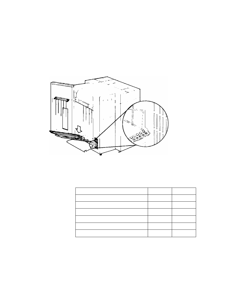
The two labels on the paper tray show you where to position the
backstop for different paper sizes. Refer to Table 4-1 for the correct
placement for your paper size and then install the backstop at the
desired location on the paper tray (Figure 4-2).
2. Position the backstop.
Figure 4-2. Positioning the Backstop
Table 4-1. Recommended Backstop Positions
Form Size (width x length)
Single Part
Multi-Part
14 g X 12 inches
E
D
14 1 X 11 inches
E
E
9 g X 11 inches
E
E
8 1 x 1 1 inches (3 hole)
E
E
11 X 8 1 inches
G
F
8 1 X 7 1 inches
I
H
4-2 USING THE POWERED PAPER STACKER
This manual is related to the following products: