I/o panel, Figure a-9. i/o panel removal – Dell Latitude Xpi CD User Manual
Page 106
A-24
Dell Latitude XPi CD Service Manual
I/O Panel
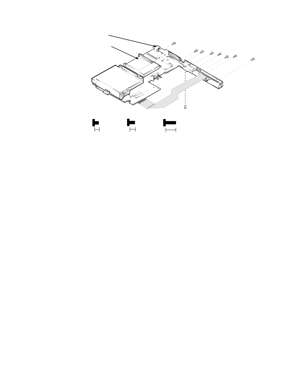
Figure A-9. I/O Panel Removal
To remove and replace the I/O panel, follow these steps:
1. Remove the I/O board.
See the previous subsection in this appendix.
2. Remove the standoff nuts ST1 through ST8
Use a
3/16
nut driver to remove standoff nuts ST1 through ST6 and a
7/32
nut
driver for ST7 and ST8.
3. Remove screw D5.
4. Remove the I/O bracket from the system board.
system board
I/O bracket
8 mm
ST5
ST6
ST7 (4 mm)
4 mm
3 mm
D5 (3 mm)
ST4
ST3
ST2 ST1
ST8 (4 mm)
NOTE: ST1–ST8 are
8-mm standoff nuts
See also other documents in the category Dell Notebooks:
- Latitude E6410 (52 pages)
- Latitude E6410 (8 pages)
- Latitude D630 (218 pages)
- Latitude E6400 (99 pages)
- Latitude E6400 (70 pages)
- Latitude E6400 (4 pages)
- Latitude E6400 (2 pages)
- Latitude E6400 (8 pages)
- Latitude D630 (69 pages)
- Latitude D630 (168 pages)
- Latitude D630 (43 pages)
- Latitude D620 (43 pages)
- Latitude D620 (102 pages)
- Inspiron 1545 (51 pages)
- Inspiron 1545 (72 pages)
- Inspiron 1545 (4 pages)
- LATITUDE C510 (55 pages)
- LATITUDE C510 (170 pages)
- Inspiron 1200 (45 pages)
- Latitude D531 (Mid 2007) (46 pages)
- Latitude D531 (224 pages)
- Inspiron 1300 (142 pages)
- Inspiron 1300 (44 pages)
- INSPIRON 2600 (134 pages)
- INSPIRON 2600 (87 pages)
- INSPIRON 2600 (168 pages)
- INSPIRON 2600 (2 pages)
- Inspiron 1100 (40 pages)
- Inspiron 1100 (164 pages)
- Inspiron 5150 (160 pages)
- Inspiron E1505 (186 pages)
- Inspiron E1505 (45 pages)
- Inspiron 1150 (38 pages)
- Inspiron 1150 (112 pages)
- Inspiron M5040 (2 pages)
- Inspiron 3520 (72 pages)
- A860 (96 pages)
- 1000 (98 pages)
- STREAK 7 (141 pages)
- XPS 14Z (L412z) (2 pages)
- Latitude D520 (99 pages)
- Latitude D520 (42 pages)
- Latitude D520 (124 pages)
- Latitude D520 (96 pages)
- Latitude D520 (168 pages)