I/o board, Figure a-8. i/o board removal – Dell Latitude Xpi CD User Manual
Page 105
Factory Repair Parts
A-23
I/O Board
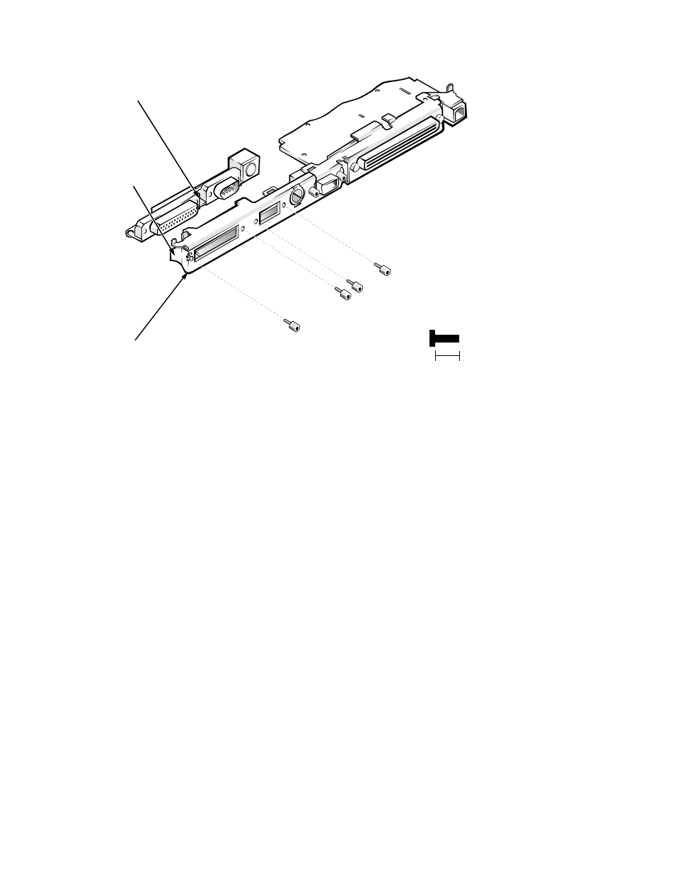
Figure A-8. I/O Board Removal
To remove and replace the I/O board, follow these steps:
1. Remove the I/O interface cable from connector JSTDIO.
See the previous subsection in this appendix.
2. Remove the keyboard/keypad/mouse connector shield.
See “Keyboard/Keypad/Mouse Connector Shield” found earlier in this
appendix.
3. Remove the four hexagonal standoff screws ST1 through ST4 that
secure the serial and parallel port connectors to the I/O panel.
Use a
3/16
nut holder to remove the standoff screws.
4. Remove the side I/O bracket clip.
See “System Board Assembly” in Chapter 4.
5. Lift the I/O board away from the I/O panel.
When replacing the I/O board, make sure that the side I/O bracket clip is
positioned so that it rests directly on the I/O board, rather than between the
I/O board and I/O bracket (see Figure A-8).
I/O board
I/O bracket
8 mm
I/O bracket clip
ST1 (8 mm)
ST2 (8 mm)
ST3 (8 mm)
ST4 (8 mm)
- Latitude E6410 (52 pages)
- Latitude E6410 (8 pages)
- Latitude D630 (218 pages)
- Latitude E6400 (99 pages)
- Latitude E6400 (70 pages)
- Latitude E6400 (2 pages)
- Latitude E6400 (8 pages)
- Latitude E6400 (4 pages)
- Latitude D630 (168 pages)
- Latitude D630 (43 pages)
- Latitude D630 (69 pages)
- Latitude D620 (43 pages)
- Latitude D620 (102 pages)
- Inspiron 1545 (72 pages)
- Inspiron 1545 (4 pages)
- Inspiron 1545 (51 pages)
- LATITUDE C510 (55 pages)
- LATITUDE C510 (170 pages)
- Inspiron 1200 (45 pages)
- Latitude D531 (Mid 2007) (46 pages)
- Latitude D531 (224 pages)
- Inspiron 1300 (44 pages)
- Inspiron 1300 (142 pages)
- INSPIRON 2600 (168 pages)
- INSPIRON 2600 (2 pages)
- INSPIRON 2600 (134 pages)
- INSPIRON 2600 (87 pages)
- Inspiron 1100 (164 pages)
- Inspiron 1100 (40 pages)
- Inspiron 5150 (160 pages)
- Inspiron E1505 (45 pages)
- Inspiron E1505 (186 pages)
- Inspiron 1150 (38 pages)
- Inspiron 1150 (112 pages)
- Inspiron M5040 (2 pages)
- Inspiron 3520 (72 pages)
- A860 (96 pages)
- 1000 (98 pages)
- STREAK 7 (141 pages)
- XPS 14Z (L412z) (2 pages)
- Latitude D520 (124 pages)
- Latitude D520 (96 pages)
- Latitude D520 (168 pages)
- Latitude D520 (99 pages)
- Latitude D520 (42 pages)