Dell POWEREDGE M1000E User Manual
Page 586
24-4
Cisco Catalyst Blade Switch 3130 and 3032 for Dell Software Configuration Guide
OL-13270-03
Chapter 24 Configuring IGMP Snooping and MVR
Understanding IGMP Snooping
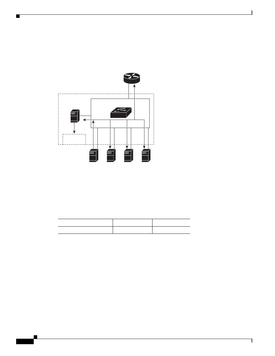
the group if it is not already present. The CPU also adds the interface where the join message was
received to the forwarding-table entry. The blade server associated with that interface receives multicast
traffic for that multicast group. See
Figure 24-1
Initial IGMP Join Message
Router A sends a general query to the switch, which forwards the query to ports 3,5, and 7, which are
all members of the same VLAN. Blade Server 1 wants to join multicast group 224.1.2.3 and multicasts
an IGMP membership report (IGMP join message) to the group. The switch CPU uses the information
in the IGMP report to set up a forwarding-table entry, as shown in
, that includes the port
numbers of Blade Server 1 and the router.
The switch hardware can distinguish IGMP information packets from other packets for the multicast
group. The information in the table tells the switching engine to send frames addressed to the 224.1.2.3
multicast IP address that are not IGMP packets to the router and to the host that has joined the group.
Forwarding
table
CPU
Router A
IGMP report 224.1.2.3
VLAN
Switching engine
19
0
1
3
5
7
201772
Blade
Server 1
Blade
Server 2
Blade
Server 3
Blade
Server 4
Table 24-1
IGMP Snooping Forwarding Table
Destination Address
Type of Packet
Ports
224.1.2.3
IGMP
19, 1