Troubleshooting procedures, 1 general, Chapter 5 – Cabletron Systems CSMIM-T1 User Manual
Page 85: General -1, Chapter 5 troubleshooting procedures, Csmim-t1 hardware installation guide 5-1, Figure 5-1 csmim-t1 front panel
CSMIM-T1 Hardware Installation Guide
5-1
CHAPTER 5
TROUBLESHOOTING PROCEDURES
5.1
GENERAL
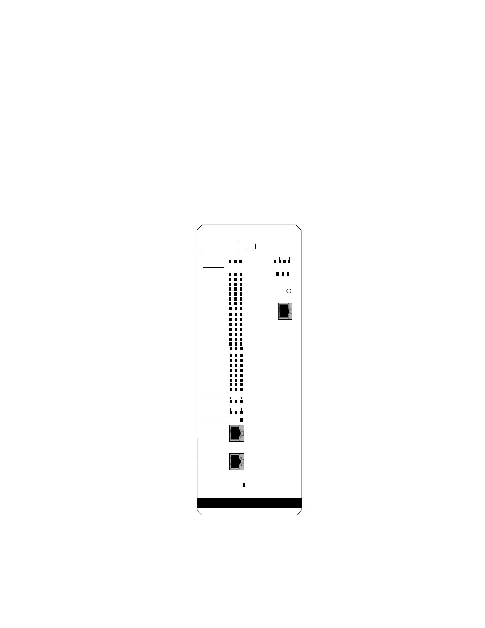
The CSMIM-T1’s front panel contains a number of LEDs that provide
information about normal operations and about problems that occur. Use
these LEDs and the ROM Monitor commands to diagnose problems.
Figure 5-1 illustrates the CSMIM-T1’s front panel LEDs.
Figure 5-1
CSMIM-T1 Front Panel
CSMIM-T1
SN
1
2
3
4
5
6
7
8
CD TX RX
16
15
14
13
12
11
10
9
MODEM
PORT
STATUS
24
23
22
21
20
19
18
17
1-8 17-24
9-16
MODEM
CONFIG
STATUS
TEST LOS
SYNC
RED BLU
YEL
NETWORK
STATUS/
ALARMS
ON LINE
DROP/INSERT
INTERFACE
T1 NETWORK
INTERFACE
DI SYNC
ETHERNET
STAT S/U
ATTN TRAF
A B C
SET UP
CONSOLE
See also other documents in the category Cabletron Systems Hardware:
- FOT-F3 (41 pages)
- FOT-F3 (44 pages)
- BRIM-F6 (41 pages)
- WPIM-RT1 (50 pages)
- BRIM-WT1 (32 pages)
- 36 (33 pages)
- 9T101-04 (28 pages)
- FDDI Repeater (29 pages)
- SWPIM-BRI (34 pages)
- 9C114 (26 pages)
- SMARTSWITCH ROUTER 9032578-05 (398 pages)
- HSIM-W6 (258 pages)
- NB25 E (30 pages)
- HSIM-G01 (36 pages)
- HSIM-FE6 (42 pages)
- Expansion module 9E429-36 (18 pages)
- EMM-E6 Ethernet (205 pages)
- Environmental Module TM 9C300-1 (50 pages)
- NBR-620 (73 pages)
- E2100 (42 pages)
- KBU64 Rackmount (26 pages)
- AirConnect 3Com (93 pages)
- 802.1Q (92 pages)
- W85 (60 pages)
- ELS10-26 (170 pages)
- Expansion module 9E106-06 (40 pages)
- 6H259-17 (58 pages)
- Expansion module 9F120-08 (12 pages)
- EMC39-12 (33 pages)
- 6A000/ZX-250 (268 pages)
- Expansion module DELHE-UA (50 pages)
- Expansion module 9T122-08 (36 pages)
- DMS-100 (196 pages)
- BRIM E100 BRIM-E100 (42 pages)
- Cabletron CyberSWITCH CSX400 (275 pages)
- Cabletron SmartSwitch Router 250 (34 pages)
- Network Router (100 pages)
- 9W111-08 (28 pages)
- CSX400 (101 pages)
- Cabletron SmartSwitch Router 510 (106 pages)
- SEHI-32/34 (90 pages)
- SmartSwitch (338 pages)
- 9T106-01 (28 pages)
- Switch 9H531-17 (38 pages)