Caution – John Deere stx38 User Manual
Page 304
8 - 18
3/21/97
MOWER DECKS
MISCELLANEOUS
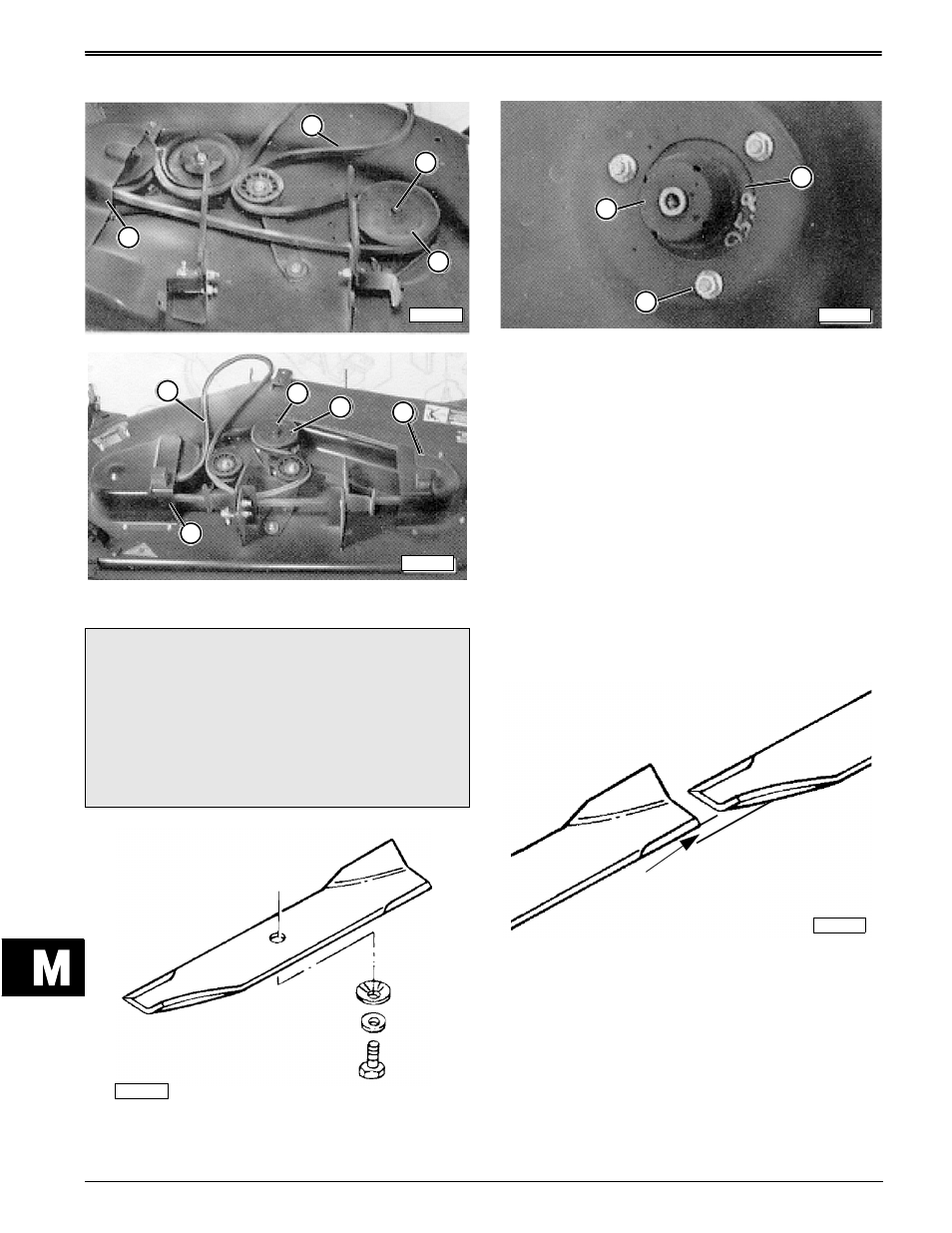
1. Remove shield(s) (D) and belt (A). DO NOT remove
nuts (B) or sheaves (C) from spindles.
2. Remove cap screw (H), small washer (G), bellville
washer (F) to remove blade(s) (E).
3. Remove spindle bearing guard(s) (I) and mounting
hardware (K) to remove any spindle assembly (J).
Inspect spindle assemblies for broken welds or
bent flanges. Replace parts as necessary.
4. Install each spindle assembly in reverse order.
Tighten mounting hardware to specification.
5. Install spindle bearing guard(s) and blade(s) to
specification.
6. Install belt (A) and shield(s) (D), as shown.
IMPORTANT: DO NOT add grease to spindle
grease fitting. They are for manufacturers use
only. Adding grease may damage spindle seals.
Specifications:
Spindle Assembly Nuts
. . . . . . . . . . . . . . . . . 23—30 N•m (200—265 lb-in.)
Blade Cap Screw . . . . . . . 46—60 N•m (34—44 lb-ft).
7. With new spindles and blades installed, check
blade alignment by measuring the difference in
height, from one lower tip to the other tip.
Specifications:
Blade difference . . . . . . . . . . . . . . . . . 6 mm (1/4 in.)
c
CAUTION
Blades are sharp and could cause personal
injury. Wear gloves or wrap blades with shop
cloths to remove and install blades. DO NOT
hold blade with bare hand. Use a block of wood
wedged between deck and blade to keep spindle
from turning.
M55889
A
B
C
D
M58341
D
B
C
D
A
M58340
M55887
K
J
I
M85800
Difference in
blade lower tips