John Deere stx38 User Manual
Page 265
3/21/97
6 - 33
HYDROSTATIC POWER TRAIN
REPAIR
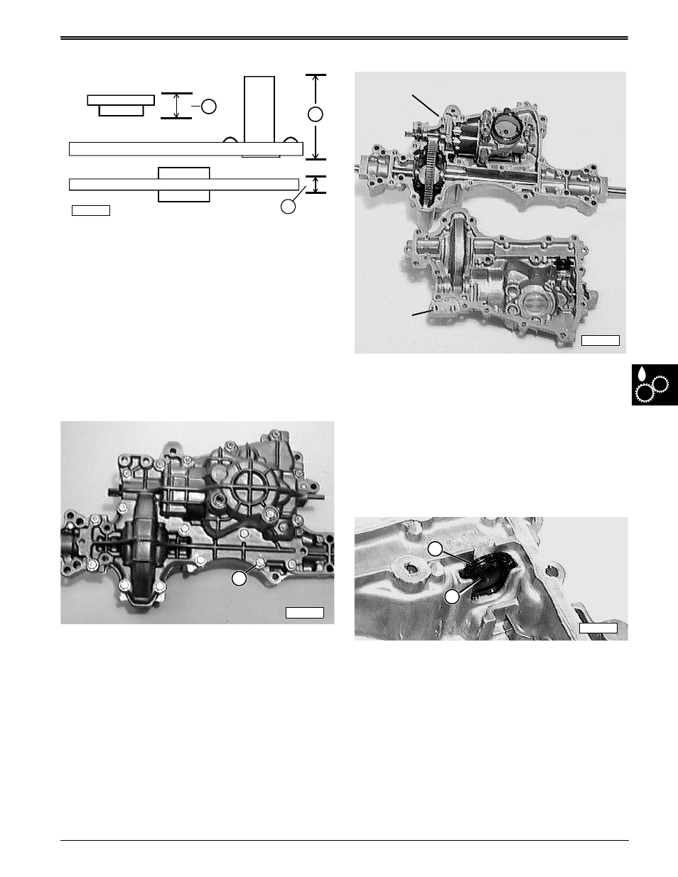
6. Measure brake components individually.
7. Replace components as necessary and as a set
only. Set brake assembly components aside for
final assembly. See page 6-46 Brake Pad
Adjustment.
Specifications:
Brake Components Wear Tolerances—
(G) brake puck (minimum) . . . . . . . 8 mm (0.3 in.)
(H) brake lever (minimum). . . . . . . 25 mm (1.0 in.)
(I) brake disc (minimum) . . . . . . 2.5 mm (.098 in.)
Separate Transaxle Housing Case Halves—
1. Remove seventeen transaxle housing cap screws
(B).
K-50 Version Shown
2. Carefully separate transaxle housing into upper and
lower case halves.
3. Remove any gasket residue from both case halves.
4. Inspect overall condition of components without
removing any of them. Visually target worn or
damaged parts for replacement.
5. Remove any remaining oil without removing any
components.
Clean and Inspect Magnet Assembly—
1. Pull magnet assembly from lower case half and
clean thoroughly.
2. Replace complete assembly if rubber ring (A) is
split or hard.
3. Test magnet (B) by holding a screw driver blade
close to, it should readily draw the blade to it. If
drawing force is weak, replace complete magnet
assembly.
4. Set magnet assembly aside for final assembly.
G
H
I
M58274
A
M58210
M55842
Lower Case
Half
Upper Case
Half
M55843
A
B