Brakes—assembly – John Deere stx38 User Manual
Page 232
5 - 68
3/20/97
REPAIR
POWER TRAIN
STX38 (SN 301383— ) Transaxle
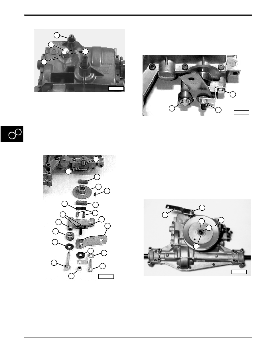
1. Install shifter shaft rubber boot (B).
2. Coat detent balls (C) and springs (D) with John
Deere Never-Seez and install in case bores.
3. Install and tighten detent cover (A) and screw until
they are flush with top of mounting hole surface.
BRAKES—ASSEMBLY
IMPORTANT: STX38 (SN 301383— ) brake
assembly differs from depiction, components
remain the same.
1. Install woodruff key (D) into shaft keyway (A).
2. Install thinner friction puck (B) in lower case puck
recess (S).
3. Install brake disc (C) with hub outward.
4. Install spacer (O) over left lip (P) of mounting
bracket.
5. Install long cap screw (M) and washer (N) in left
mounting bracket hole.
6. Install brake lever (H), washer (I), bent bracket (J),
and lock nut (L) on mounting bracket center stud.
7. Install short cap screw (K) in right mounting bracket
hole (G).
8. Install dowel pins (F) inside two center mounting
bracket holes (Q).
9. Install striker plate (R) and thick friction puck (E) in
backside recess of mounting bracket.
1. Install complete brake assembly to transaxle.
2. Tighten cap screws (K and M) to specification.
3. Tighten lock nut (L) to specification.
Specifications:
Brake Assembly Cap Screws
. . . . . . . . . . . . . . . . . 18—22 N•m (160—200 lb-in. )
Brake Assembly Lock Nut
—Tighten Until Required Air Gap Is Reached
. . . . . . . . . . . . . . . . . . 0.254 mm (0.010 in.) air gap
between thick friction puck (outside brake pad)
and brake disc (rotor).
Install Drive Sheave and Shift Arm:
1. Install woodruff key (C) in input shaft (E).
2. Install drive sheave (D) and fasten with snap ring
(F).
3. Install shift arm (A). Tighten cap screw (B) to
specification.
Specification:
Shift Arm Cap Screw
. . . . . . . . . . . . . . 13.5—17.6 N•m (120—156 lb-in.)
B
A
C
D
M88992
M42317
B
C
E
A
S
D
R
G
H
P
O
N
M
J
I
K
L
F
Q
M42314
K
M
L
M55825
C
E
D
A
F
B