Repair – John Deere stx38 User Manual
Page 210
5 - 46
3/21/97
REPAIR
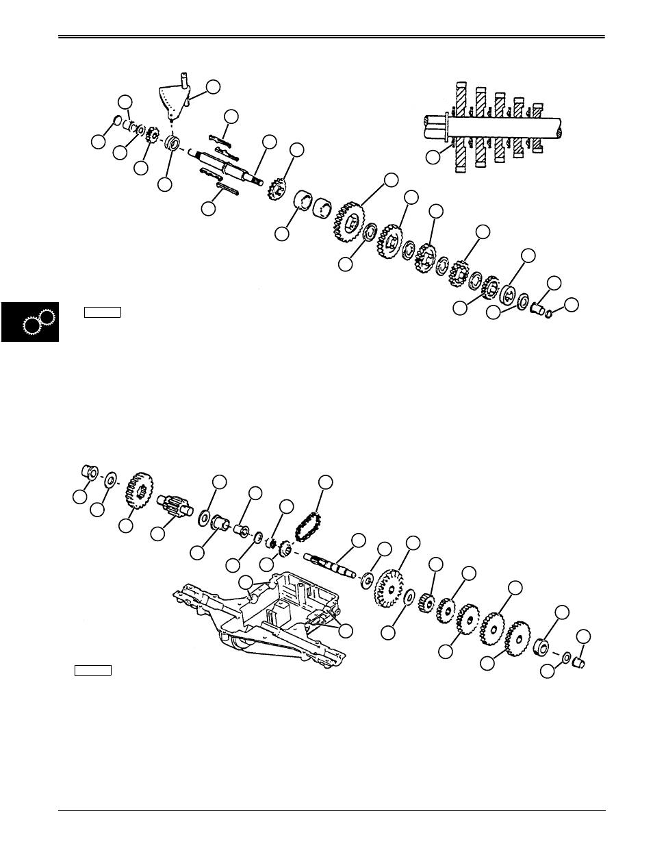
POWER TRAIN
Counter Shaft—Assemble
M52022
O
A
B
C
D
B
A
E
F
G
H
I
J
L
K
N
P
Q
R
F
K
M
E
S
S
1. Put LUBRIPLATE lubricant in keyways of shaft (G).
2. Position keys (H) near end of shaft in keyways.
Install collar (F) over keys with thicker shoulder of
collar towards shaft.
3. Install gear (E—15 teeth) with thicker shoulder
towards collar (F).
NOTE: Grease ends of shaft before installing
bushings.
4. Install washer (D), bushing (C), and disc (B).
5. Install sprocket (I) and spacers (J).
6. Raised side of washers (L) and flat side of gears
MUST face shoulder of shaft.
7. Install gears (K—15 teeth), (M—15 teeth),
(N—15 teeth), (O—15 teeth), and (P—15 teeth)
alternately with washers (L).
8. Install spacer (Q) and washer (R).
9. Install bushing (C).
10. Install seal (S).
1. Install washer (K) and gear (L) with bevel towards
center of shaft.
2. Install washer (K).
3. Install gears (M), (N), (O), (P), and (Q).
4. Install spacer (R) and washer (F).
NOTE: Grease ends of shaft before installing
bushings.
5. Install bushing (E).
6. Install gear (H).
7. Put counter and brake shaft ends together and
install chain (I).
8. Install spacer (G), washer (F), and bushing (E).
9. Install gear (C) on assembly (D).
10. Install washers (B) and bushings (A).
11. Grease points (S).
12. Install counter and brake shaft assemblies in case.
13. Install shifter fork.
Brake Shaft—Assemble
M52021
C
B
A
D
H
F
G
H
I
J
K
L
M
O
P
Q
R
C
N
E
S
L