John Deere stx38 User Manual
Page 272
6 - 40
3/21/97
REPAIR
HYDROSTATIC POWER TRAIN
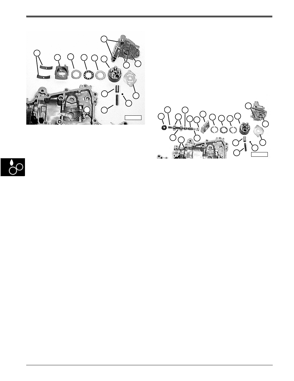
Disassemble and Inspect Pump and Swashplate—
IMPORTANT: PAY CLOSE ATTENTION to the
ORDER and ORIENTATION of ALL
COMPONENTS to their neighboring
components. Mark them, if necessary. This will
help greatly during assembly.
1. Carefully separate pump and swashplate
components.
2. Clean and inspect components individually once
disassembled:
• thrust bushings (A) should not be scored, pitted, or
worn badly—measure thickness:
Thrust bushings thickness
Minimum . . . . . . . . . . . . . . . . . . . 1.3 mm (0.05 in.)
• swashplate (B) machine surfaces of ramps and
bearing recess and bushing should not scored,
pitted, discolored, or worn badly
• swashplate roller bearing (C, D, and E) should not
be scored, pitted, discolored, missing any rollers,
or roller retainer broken
• pump cylinder block (F), pistons (L), washers (K),
and springs (M) must have free movement and
should not be scored, pitted, discolored, distorted,
or worn
• bronze pump plate (J) and mating surface of
cylinder block (F) should not be grooved,
discolored, or worn thin around ports;
• center block machined surface (I) should not
scored, pitted, or discolored
• center block rolled pins (G) and dowel pins (H)
should be in good condition, not missing or
sheared off
• upper case ramps and centering pins (N) should be
in good condition.
IMPORTANT: If thrust bushings and swashplate
ramps are damaged, they must be replaced as a
set. If swashplate recess machined surface or
bushing are damaged, replace with new
swashplate (bushing is not serviced separately).
If bronze pump plate or center block are
damaged, they both must be replaced. If any
component of pump cylinder block is damaged,
a complete new pump cylinder block must be
ordered.
Disassemble and Inspect Motor and Drive Shaft—
IMPORTANT: PAY CLOSE ATTENTION to the
ORDER and ORIENTATION of ALL
COMPONENTS to their neighboring
components. Mark them, if necessary. This will
help greatly during assembly.
1. Carefully separate motor and drive shaft
components.
2. Clean and inspect components individually once
disassembled.
• drive shaft seal must be replaced every time drive
shaft is removed or case halves separated
• drive shaft splines (B and E) should be in good
condition, not chipped, broken, or worn
• drive shaft ball bearings (C) should not be scored,
pitted, loose, or discolored;
• drive shaft snap ring (D) should be in good
condition as should its groove
• drive shaft machined surface (R) should not be
scored, pitted, or worn
• drive shaft spur gears (T) should have 6 teeth, not
be scored, pitted, discolored, chipped or broken,
nor worn thin
• drive shaft-to-cylinder block spring (F) should be in
good condition, not weak, broken, nor distorted
M58217
A
B
D
E
J
C
L
K
N
F
M
I
G
H
M58218
A
B
C
D
E
T
F
G
H
I
J
K
M
N
S
R
O
Q
P
L