Reservoir cover and breather valve—assembly, Fan and drive sheave— installation – John Deere stx38 User Manual
Page 279
3/21/97
6 - 47
HYDROSTATIC POWER TRAIN
REPAIR
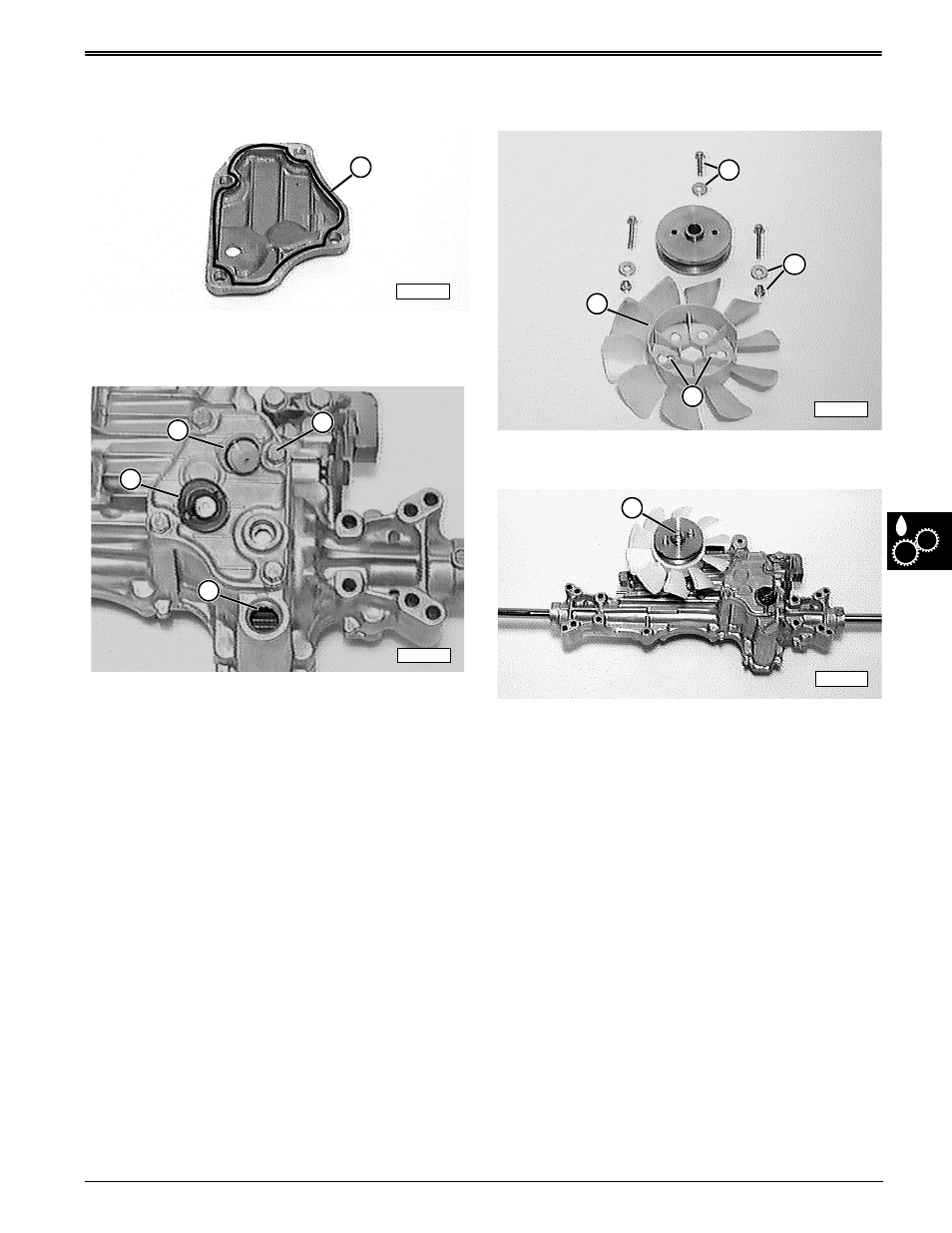
RESERVOIR COVER AND
BREATHER VALVE—ASSEMBLY
1. If reservoir cover was removed or replaced, apply a
solid bead (A) of John Deere Form-In-Place
Silicone Gasket Sealant around the cover, staying
to inside of holes.
2. Install cover to reservoir and fasten with 4 cap
screws (C). Tighten cap screws to specification.
3. Fill reservoir with 1.6 L (1.7 U.S. qt) of John Deere
Plus-4, 10W30, Class-CD engine oil. Oil should
reach bottom of fill hole (D).
4. Install breather valve assembly (E) and fill cap (B).
Specification:
Reservoir cover cap screws
. . . . . . . . . . . . . . . . . 20—24 N•m (174—217 lb-in.)
FAN AND DRIVE SHEAVE—
INSTALLATION
1. Assemble fan to transaxle drive sheave using two
fan holes (C). Two washers and nuts (B) go under
fan. Bottom fan lip (D) goes towards transaxle.
2. Install sheave/fan assembly to pump input shaft
with cap screw and washer (A). Tighten cap screw
to specification.
Specification:
Drive sheave cap screw
. . . . . . . . . . . . . . . . 13.5—20 N•m (120—168 lb-in.)
M58235
A
C
B
E
M58234
D
M58236
C
B
A
D
M58237
A