Transaxle disassembly – John Deere stx38 User Manual
Page 263
3/21/97
6 - 31
HYDROSTATIC POWER TRAIN
REPAIR
Specification:
Flange nut to right-front mounting bracket
. . . . . . . . . . . . . . . . . . . . . . . . . . 15 N•m (132 lb-in.)
Cap screw and nut to left-front mounting bracket
. . . . . . . . . . . . . . . . . . . . . . . . . 15 N•m (132 lb-in.)
Cap screws and nuts to frame
. . . . . . . . . . . . . . 20.3—47.4 N•m (180—420 lb-in.)
Shift arm cap screw and lock nut
. . . . . . . . . . . . . . . . 9.5—14.9 N•m (84—132 lb-in.)
Turnbuckle lock nut
. . . . . . . . . . . . . . . 10.8—16.3 N•m (96—144 lb-in.)
IMPORTANT: To adjust entire traction drive
system see tests and adjustments.
TRANSAXLE DISASSEMBLY
IMPORTANT: PAY CLOSE ATTENTION to the
ORDER and ORIENTATION of ALL
COMPONENTS to their neighboring
components. Mark them, if necessary. This will
help greatly when its assembly time.
Remove Drive Sheave and Fan—
1. Thoroughly clean transaxle with approved solvent
for aluminum castings and dry with compressed
air.
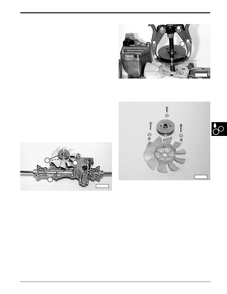
2. Remove fan cap screws and flange nuts (A).
3. Remove cap screw and washer (B).
4. Reference transaxle serial number (C) whenever
necessary.
5. Install an 19m8334 (M6x1.0x30) socket head cap
screw (D) from stock into end of pump (input)
shaft—finger tight only.
6. Put puller on special screw and pull drive sheave
from pump shaft.
7. Inspect drive sheave for damage, replace as
necessary.
8. Remove fan and inspect for damage, replace as
necessary.
A
M58237
C
B
M58204
D
M58236