Repair – John Deere stx38 User Manual
Page 224
5 - 60
3/20/97
REPAIR
POWER TRAIN
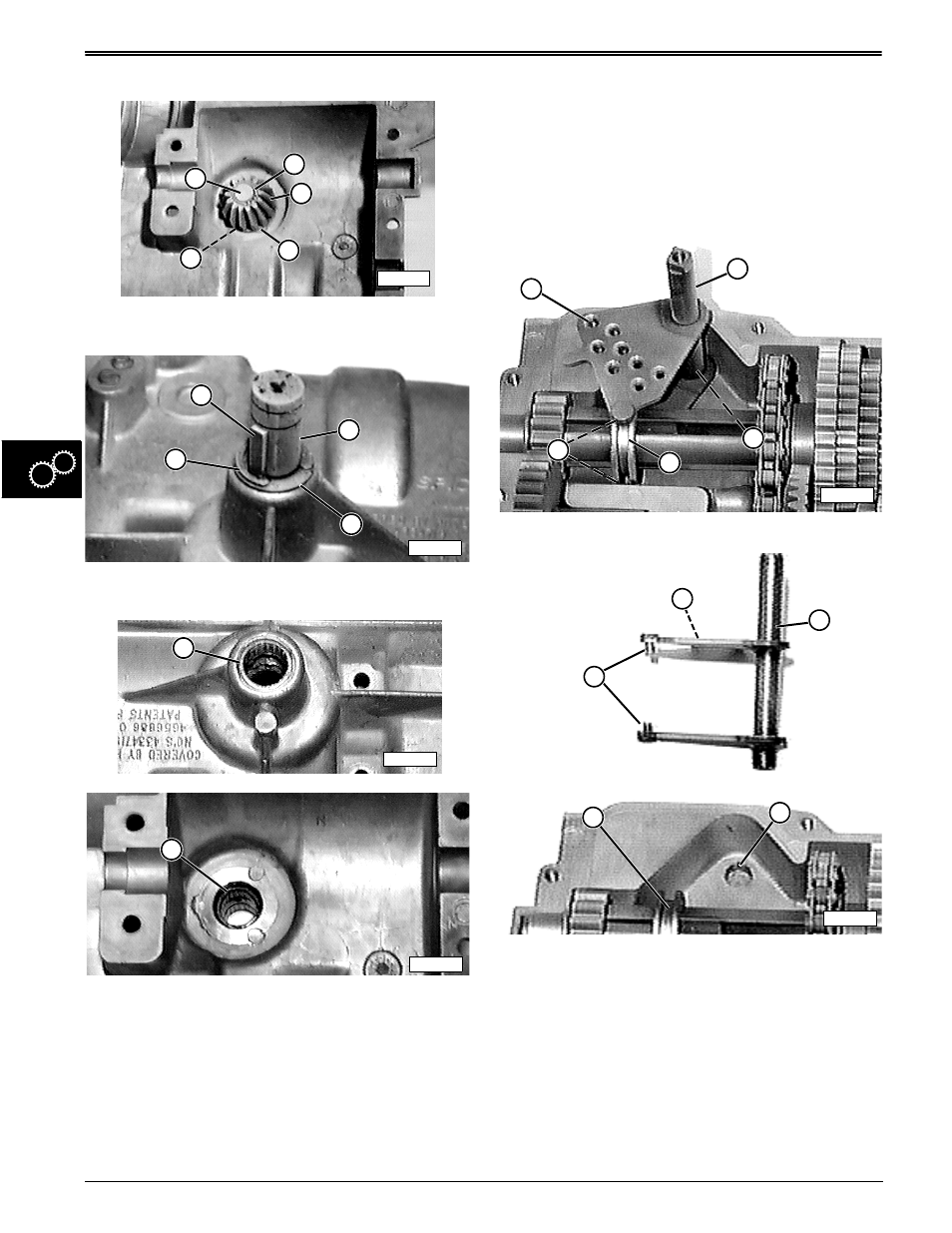
Disassemble Input Shaft/Pinion Gear Assembly:
1. Remove snap ring (B), bevel pinion gear (C), small
washer (E), and large washer (D) from input shaft
(A), inside upper case half.
2. Turn upper case half over.
3. Remove woodruff key (F), E-ring (I), shim washer
(H), and input shaft (G).
IMPORTANT: DO NOT scratch or deform upper
case half bore when removing needle bearings.
4. Visually inspect condition of upper case half input
shaft needle bearings, upper bearing (J) and lower
bearing (K).
5. Measure inside diameters of each bearing:
• “GO” measurement should be 15.89—15.92 mm
(0.6255—0.6269 in.)
• “NO GO” measurement is anything greater.
6. If measurement results in a “NO GO” reading for
either bearing, replace both bearings (ordered as
set with special grease) by carefully pressing them
from case half bore without damaging bore.
7. Clean and inspect bore. If scratched or deformed,
replace upper case half.
Disassemble Shifter Shaft Assembly:
1. Lift shifter shaft assembly (B) from lower case half
mounting hole (C) and groove of shift collar (D).
2. Clean shifter shaft assembly once removed.
3. Inspect condition of detent holes (A), shift pins (E),
overall shifter shaft assembly (B), lower case half
mounting hole (C), and shift collar (D).
4. If any part of shifter shaft assembly (B) is worn or
damaged, replace it; also, the rubber boot, and the
detent balls, detent springs, and set screws (see
Service Kits listing at beginning of section).
5. If lower case half mounting hole (C) is worn or
damaged, replace the case half.
6. If shift collar (D) is worn or damaged, replace it
when intermediate shaft assembly is
disassembled.
B
C
D
M42320
E
A
M42313
G
H
I
F
M42497
J
M42496
K
M42322
B
A
E
C
D
E
B
C
D
A
M42323