John Deere stx38 User Manual
Page 294
8 - 8
3/21/97
MOWER DECKS
MISCELLANEOUS
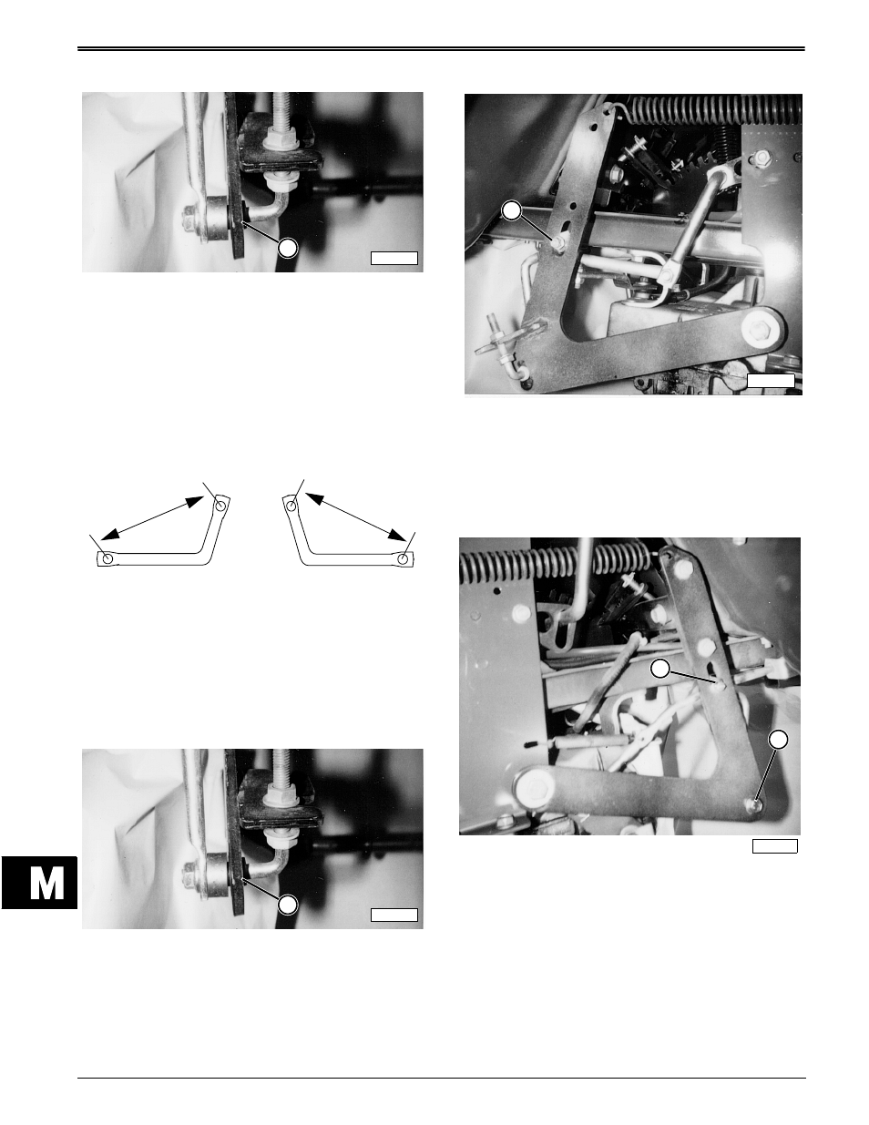
7. Install LH Bracket (M116689) on the right side of
tractor. Fasten lower end of bracket (A) with nut
removed in Step 4.
8. Fasten upper end of bracket (B) to slot in lift arm
with M6x20 cap screw and lock nut. Tighten lock
nut.
9. Replace rear tires and lower machine safely to
ground.
STX38 (M00STXB139616—210000)
1. Reshape RH bracket (M116688) to 135 mm (5.3
in.) hole centers.
2. Reshape LH bracket (M116689) to 117 mm (4.6 in.)
hole centers.
3. Park tractor on level surface. Engage park brake.
4. Raise rear of tractor onto jack stands. Remove rear
wheels.
5. Remove nut and old bracket from roller assemblies
on both sides of tractor.
6. Install RH Bracket (M11688) on left side of tractor.
Fasten lower end of bracket (A) with nut removed
in Step 5.
7. Fasten upper end of bracket (B) to slot in lift arm
with M6x20 cap screw and locknut. Tighten
locknut to contact, then loosen 1 turn.
NOTE: Bracket must be free to move up or down in
slot when roller is moved during side-to-side
mower deck leveling adjustment.
8. Drill 1/4 in. hole in right side lift arm, 4.6 in. (117
mm) above hole for existing roller assembly.
9. Install LH Bracket (M116689) on the right side of
tractor. Fasten lower end of bracket (A) with nut
removed in Step 4.
10. Fasten upper end of bracket (B) to slot in lift arm
with M6x20 cap screw and lock nut. Tighten lock
nut.
11. Replace rear tires and lower machine safely to
ground.
M85801
A
117 mm
135 mm
(4.6 in.)
(5.3 in.)
M85801
A
M85802
B
M85803
B
A