John Deere stx38 User Manual
Page 222
5 - 58
3/20/97
REPAIR
POWER TRAIN
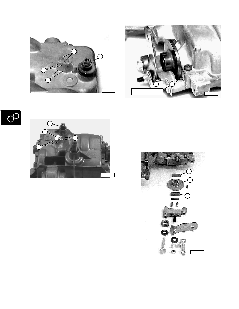
Remove Shifter Detent Assembly
STX38 (SN 210001—301382) and STX46 Transaxle
1. Remove shifter shaft rubber boot (E).
2. Remove both set screws (D) and detent springs
(G).
STX38 (SN 301383— ) Transaxle
1. Remove shifter shaft rubber boot (E).
2. Remove detent cover (D) and detent springs (G).
IMPORTANT: DO NOT drop or lose detent balls.
3. Use a magnet or place a shop cloth over holes and
turn transaxle upside-down to catch both detent
balls (F) in cloth.
4. Inspect detent balls and springs for wear or
damage. Replace components as necessary, but
do not install until assembly, much later in this
section.
Remove Brake Assembly:
IMPORTANT: First check brake components for
wear. Check for brake disc contacting the case
(1) and/or brake lever contacting its mounting
bracket (2), top or bottom. If so, all three
components must be replaced.
NOTE: STX38 (SN 210001—301382) and STX46
brake assembly is depicted below. STX38 (SN
301383— ) brake assembly differs slightly,
but main components remain the same.
1. Remove brake assembly.
2. It is recommended that thinner, inside, (A) and
thicker, outside, (C) friction pucks and brake disc
(B) be replaced (pucks ordered as set only)
anytime transaxle is disassembled.
3. Inspect remaining components for wear or damage.
Replace components as necessary, but do not
install this assembly until transaxle has been
completely assembled.
E
D
F
G
M42316
E
D
G
M88992
F
M58279
Contact Points
1
2
M42317
A
B
C