Repair – John Deere stx38 User Manual
Page 206
5 - 42
3/21/97
REPAIR
POWER TRAIN
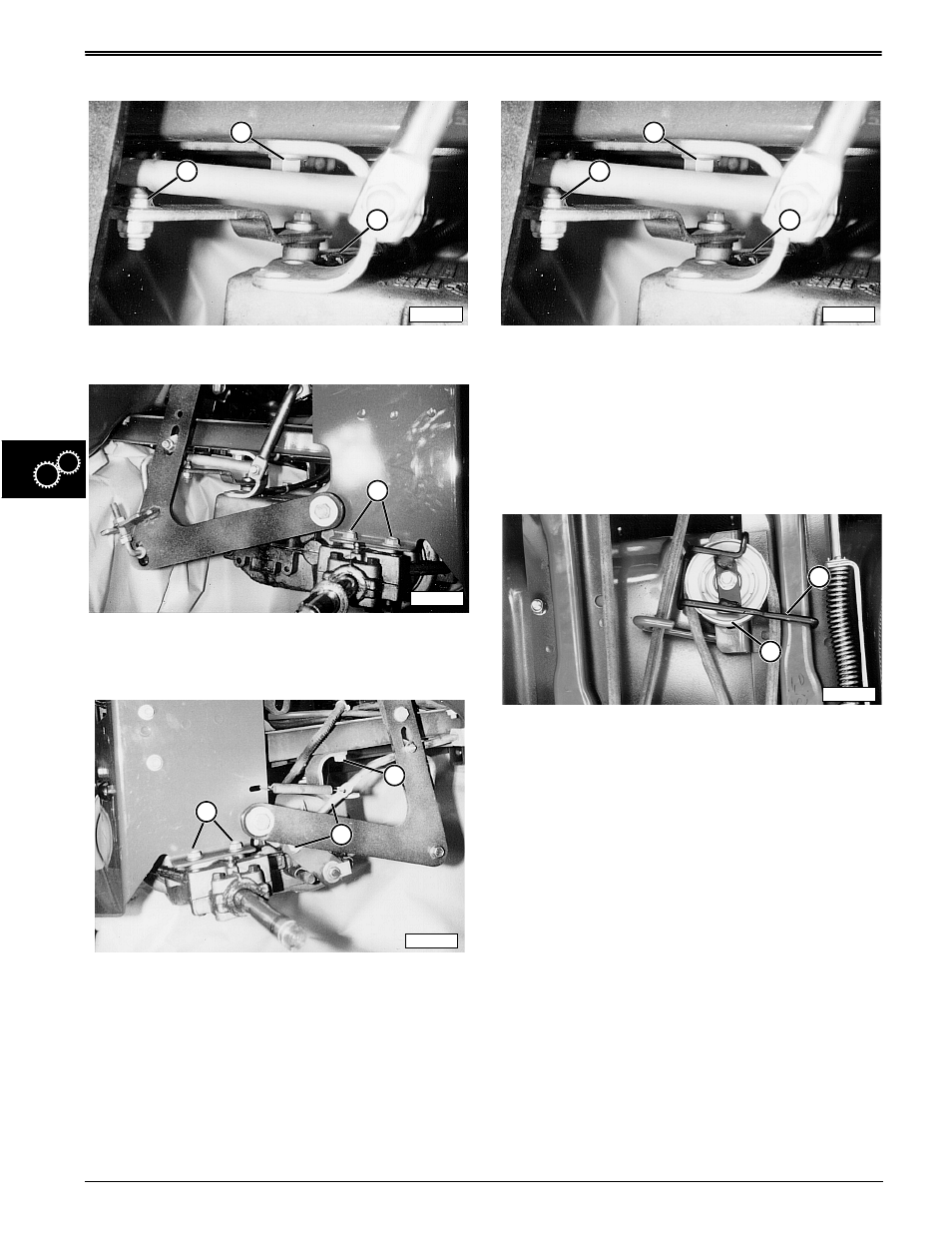
10. Disconnect linkage (C), unplug neutral start switch
(D) and remove cap screw (B) from left side of
transaxle.
11. Remove cap screws (E) and from left and right side
to remove transaxle.
Installation
1. Install transaxle using cap screws (E). Do this for
both left and right sides.
2. Connect linkage (A) and install cap screw (B) on
right side of transaxle.
Specifications:
Transaxle Mounting Cap Screws to Hanger
Bracket (Front) . . . . . . . . . . . . 15 N•m (132 lb-in.)
Transaxle Mounting Cap Screws to
Frame (Rear) . . . 20.3—47.4 N•m (180—420 lb-in.)
3. Connect linkage (C) on left side of transaxle.
4. Install cap screw (B).
5. Connect neutral start switch (D).
Specifications:
Transaxle Mounting Cap Screws to Hanger
Bracket (Front) . . . . . . . . . . . . 15 N•m (132 lb-in.)
6. Push belt through transaxle guide (not depicted).
7. Install belt on transaxle sheave (not depicted).
8. Install belt on sheave (A).
9. Engage park lever.
10. Slide sheave to remove slack from belt. Tighten
sheave cap screw.
11. Install guide (B).
12. Install wheels.
Specifications:
Sheave Cap Screw . . . . . . . . . . . . . . 95 N•m (70 lb-ft)
M85844
B
D
C
M51997
E
M51996
B
E
A
M85844
B
D
C
M52007
B
A